Flexible display panel and flexible display

a flexible display and display panel technology, applied in non-linear optics, instruments, optics, etc., can solve the problems of low optical efficiency, liquid crystal panel, and relatively high required driving voltage, and achieve the effect of avoiding undesirable displays

Active Publication Date: 2016-09-08
BOE TECH GRP CO LTD
View PDF8 Cites 1 Cited by
  • Summary
  • Abstract
  • Description
  • Claims
  • Application Information

AI Technical Summary

Benefits of technology

[0005]The technical problem to be solved by the present invention is, in view of the problem of non-uniform thickness of a liquid crystal cell of an existing flexible display panel, to provide a flexible display panel and a flexible display which can avoid undesirable display due to the non-uniform thickness of a liquid crystal cell.

Problems solved by technology

However, this type of liquid crystal panel has the disadvantages of relatively high required driving voltage and low optical efficiency.
However, the photoelectric property of blue phase liquid crystal is non-sensitive to the thickness of the liquid crystal cell, therefore, most importantly, when a flexible display panel is bent, the display effect will not be greatly influenced even though the thickness of the liquid crystal cell is changed, so that the problem of poor display effect of the flexible display panel due to non-uniform thickness of the liquid crystal cell can be solved.

Method used


Image

  • Flexible display panel and flexible display
  • Flexible display panel and flexible display

Examples


embodiment 1

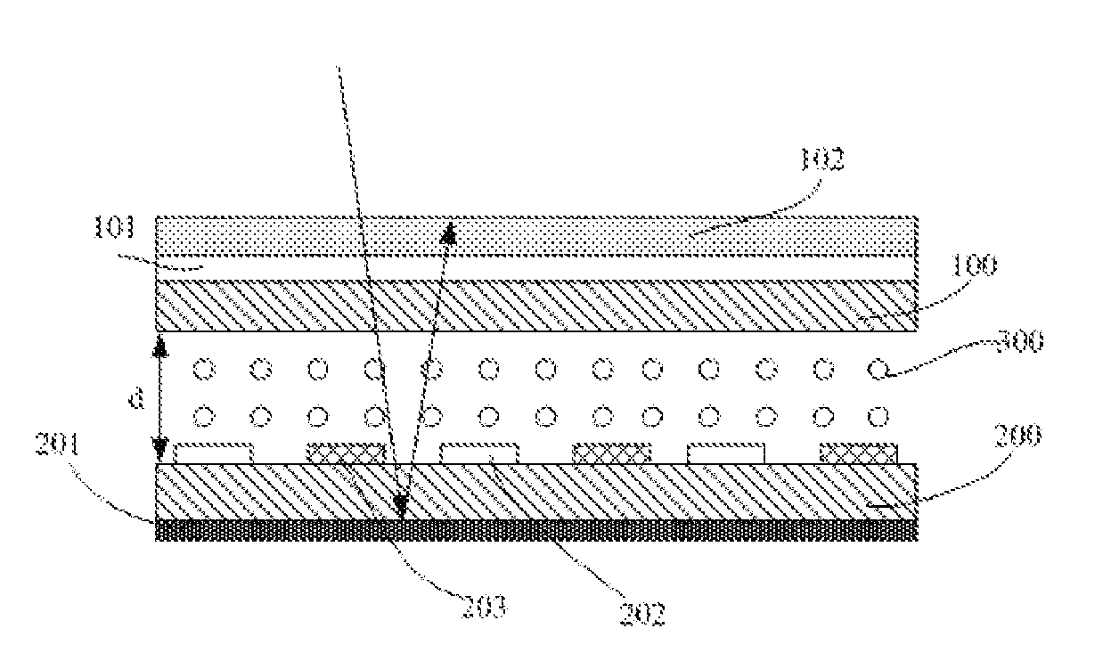
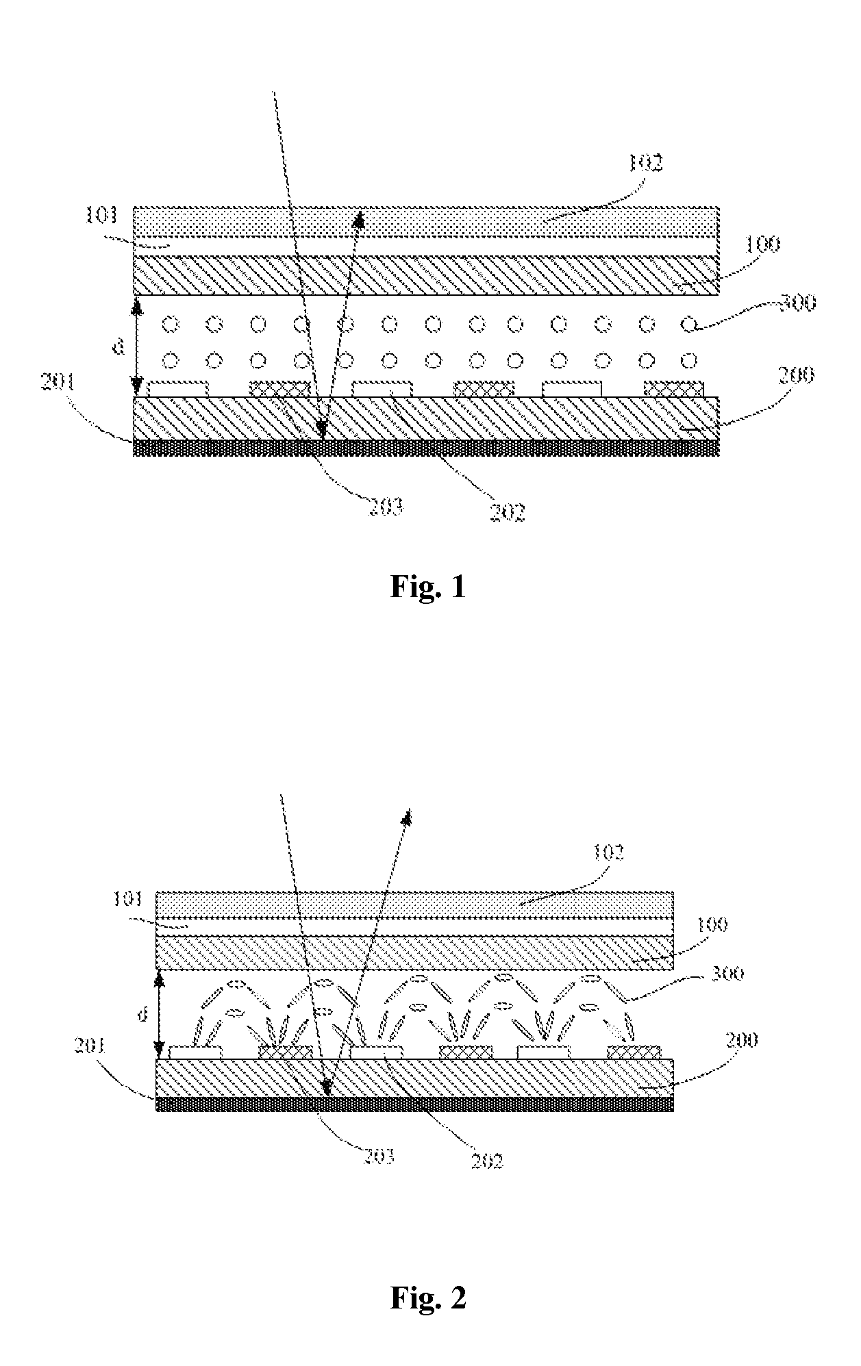
[0021]Referring to FIGS. 1 and 2, this embodiment provides a flexible display panel, comprising a first flexible substrate 100 and a second flexible substrate 200 which are cell-aligned to each other, and a blue phase liquid crystal layer 300 disposed between the first flexible substrate 100 and the second flexible substrate 200. The flexible display panel further comprises a reflective layer 201 disposed on the second flexible substrate 200 at a side far away from the blue phase liquid crystal layer 300 and strip electrodes disposed on the second flexible substrate 200 at a side close to the blue phase liquid crystal layer 300 at intervals; and, a ¼ wave plate 101 and a polarizer 102 which are successively arranged on the first flexible substrate 100 at a side far away from the blue phase liquid crystal layer 300, with an included angle between a light transmitting axis of the polarizer 102 and an optical axis of the ¼ wave plate 101 being 45° and an included angle between each of ...

embodiment 2

[0035]This embodiment provides a flexible display, comprising the flexible display panel described above. The flexible display may be any product or component having a display function, such as a mobile phone, a tablet computer, a TV set, a display, a notebook computer, a digital photo frame, a navigator, or the like.

[0036]Preferably, the flexible display provided in this embodiment further comprises a front light source disposed on a front frame of the flexible display. The front light source may allow light to irradiate on the flexible display panel, so that the flexible display may also perform display in a dark environment.

[0037]The flexible display provided in this embodiment has the flexible display panel provided in Embodiment 1, so the cost of the flexible display is low.

[0038]Of course, the flexible display provided in this embodiment may further comprise other conventional structures, such as a power supply unit, a display driving unit, and the like.


PUM

PropertyMeasurementUnit
included angleaaaaaaaaaa
widthaaaaaaaaaa

Abstract

A flexible display panel, comprising: a first flexible substrate and a second flexible substrate cell-aligned to each other; a blue phase liquid crystal layer disposed between the first flexible substrate and the second flexible substrate and strip electrodes arranged on the second flexible substrate at a side close to the blue phase liquid crystal layer at intervals; a reflective layer disposed on the second flexible substrate at a side far away from the blue phase liquid crystal layer; and a ¼ wave plate and a polarizer successively arranged on the first flexible substrate at a side far away from the blue phase liquid crystal layer, with an included angle between a light transmitting axis of the polarizer and an optical axis of the ¼ wave plate being 45° and an included angle between each of the strip electrodes and the optical axis of the ¼ wave plate being 90°.

Description

FIELD OF THE INVENTION[0001]The present invention relates to the field of flexible display technology, in particular to a flexible display panel and a flexible display.BACKGROUND OF THE INVENTION[0002]At present, Liquid Crystal Displays (LCDs) have become mainstream display products in market due to their excellent performances and mature technologies.[0003]As one key component in a liquid crystal display, a liquid crystal panel is mainly formed by cell alignment of a color filter substrate and an array substrate, and liquid crystal is filled between the color filter substrate and the array substrate to form a liquid crystal cell. In order that the liquid crystal panel can realize normal display, liquid crystal is required to have a function of changing the polarization state of light, that is, the polarization state of light is changed by an optical delay generated by the liquid crystal and thus bright and dark display is realized. Moreover, the function of the liquid crystal of ch...

Claims


Application Information

Patent Timeline
Patent Type & Authority Applications(United States)
IPC IPC(8): G02F1/1333G02F1/1343G02F1/13363G02F1/1335
CPCG02F1/133305G02F1/133308G02F1/133514G02F1/133553G02F1/133528G02F1/134309G02F2001/133616G02F1/13363G02F1/1336G02F1/133371G02F2001/13332G02F2001/133354G02F2001/133638G02F1/13439G02F1/134363G02F1/133616G02F1/133638G02F1/13793G02F1/13332G02F1/133354
Inventor ZHAO, WEILI
Owner BOE TECH GRP CO LTD
Why Eureka
Try Eureka