
Systems and methods for measuring phase dynamics and other properties

a technology of applied in the field of systems and methods for measuring phase dynamics and other properties, can solve problems such as errors and uncertainties, errors, and noise level and stability, and achieve the effects of reducing the accuracy of system outpu

Active Publication Date: 2016-09-15
NASA
View PDF0 Cites 2 Cited by
  • Summary
  • Abstract
  • Description
  • Claims
  • Application Information

AI Technical Summary

Benefits of technology

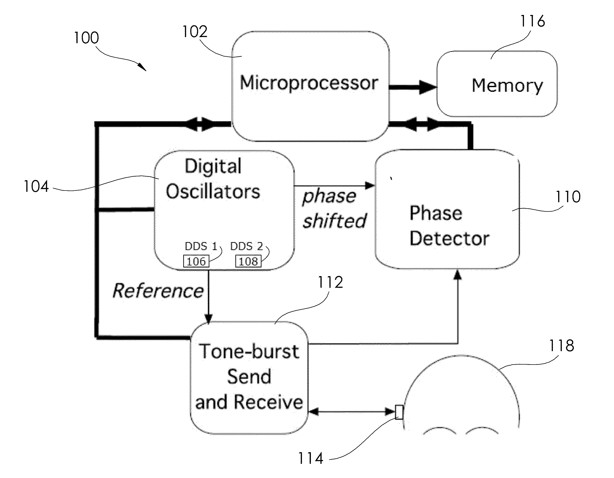
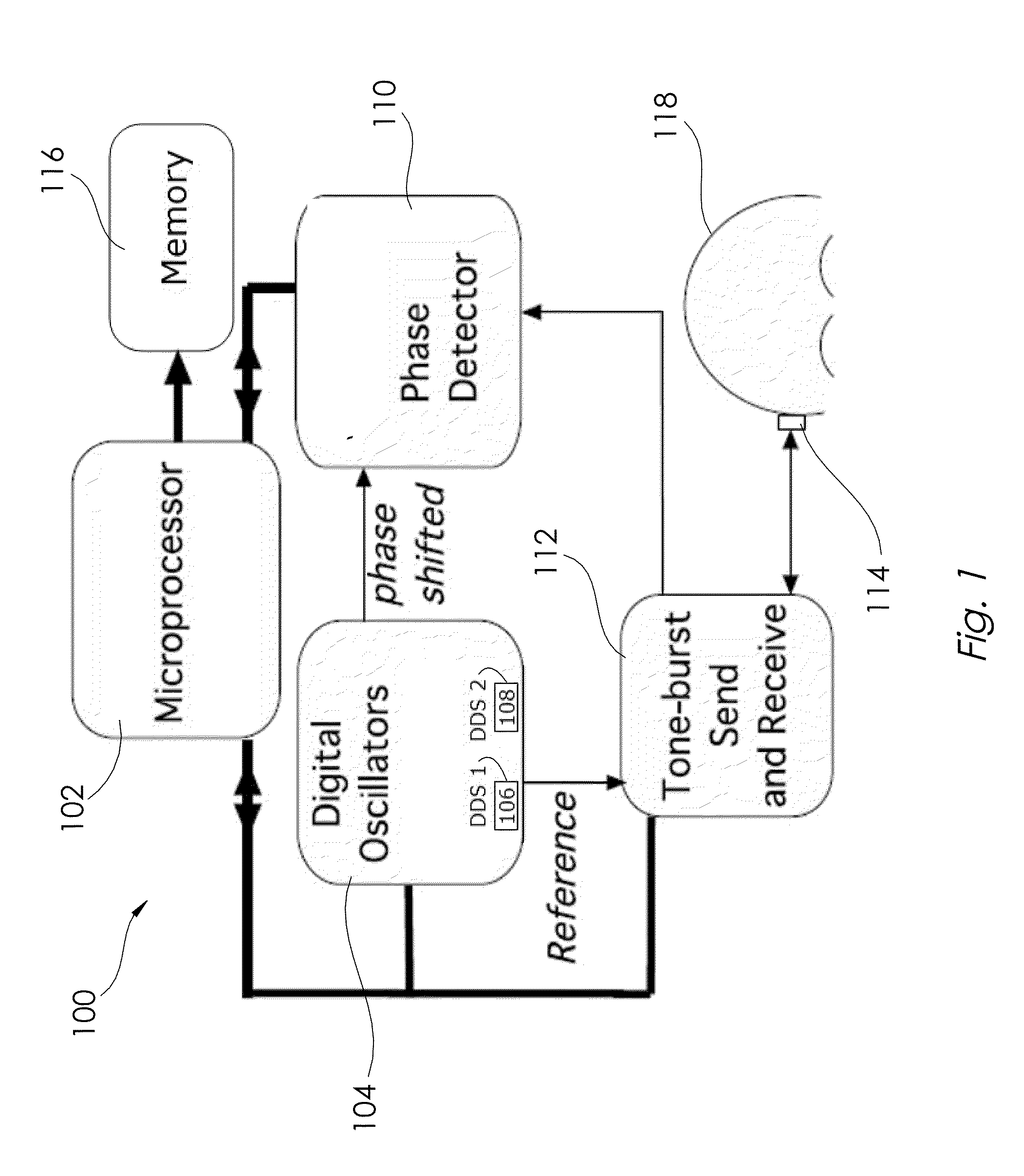
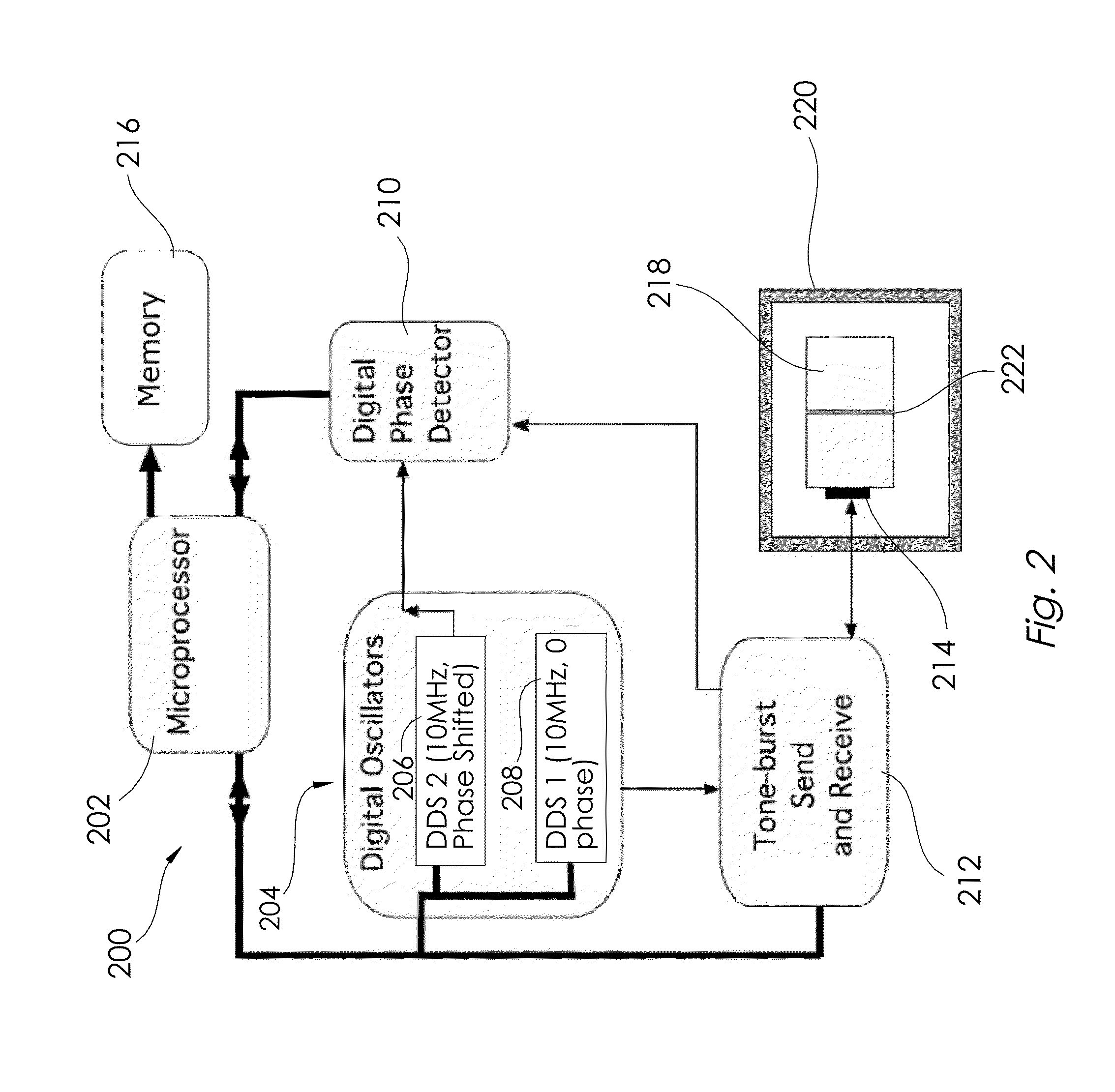
The patent describes a system and method for measuring the movement of a sample using a processor and a digital oscillator module. The system includes a transducer module that generates a measurement waveform with a constant frequency and a linear phase detector that measures the phase difference between the measurement waveform and a reference waveform. The system can adjust the phase difference to match the phase of the received waveform. The system can also send and receive additional tone-bursts to further analyze the sample. The measurement methods can be used to determine the rate of skull volume expansion, total fluid volume present in the skull, and intracranial pressure of a sample. The system can record the phase difference and bond characteristics of the sample.

Problems solved by technology

These methods, however, suffer from drawbacks, including problems with accuracy, precision, noise level and stability.
This creates errors as well as uncertainties, as the PPLL systems operate under that assumption that the quadrature phase detectors respond only to phase changes in the signal path relative to the reference oscillator path.
What's more, reflections from the skull also shift phase due to frequency changes, and therefore also create unintended and unaccounted phase-shift contributions to the systems output.
Another drawback is that the quadrature phase detector prevents the measurement technology from measuring phase differences linearly, and therefore cannot provide numerical output in phase.

Method used


Image

  • Systems and methods for measuring phase dynamics and other properties
  • Systems and methods for measuring phase dynamics and other properties
  • Systems and methods for measuring phase dynamics and other properties

Examples


Embodiment Construction

[0031]The examples, systems, apparatuses and methods of described herein provide systems and / or methods for measuring properties, relationships, and / or dynamics. These and other aspects, features and advantages of the disclosure or of certain embodiments of the disclosure will be further understood by those skilled in the art from the following description of example embodiments. In the following description of various examples, reference is made to the accompanying drawings, which form a part hereof. It is to be understood that other modifications may be made from the specifically described methods and systems without departing from the scope of the present disclosure.

[0032]In accordance with one aspect, measurement systems are provided. As described in more detail below, these systems may offer new analytical capabilities for assessment of, e.g., intracranial dynamics and / or other properties. One or more disclosed systems may be utilized to monitor of trans-cranial expansion and r...


PUM


Abstract

Systems and methods for measuring phase dynamics and other properties (e.g. intracranial pressure) are disclosed. For example, the system may generate a reference waveform and a measurement waveform using digital synthesizers, each waveform having an identical constant frequency but also a relative phase shift. Next, system may send a tone-burst, via a transducer, into a sample (e.g. a skull or a bonded material), and then receive a reflected tone-burst in response. Then, a phase difference between the received tone-burst and the measurement waveform may be determined with a linear phase detector. Next, the phase shift of the measurement waveform may be adjusted, by the determined phase difference, such that there is no longer any phase difference between the received tone-burst and the adjusted measurement waveform generated by the appropriate digital synthesizer. A similar adjustment may occur after subsequent tone-bursts, allowing accurate monitoring of continuously variable phase relationships.

Description

CROSS-REFERENCE TO RELATED PATENT APPLICATION(S)[0001]This patent application claims the benefit of and priority to U.S. Provisional Patent Application No. 62 / 131,397, filed on Mar. 11, 2015, the contents of which are hereby incorporated by reference in their entirety.STATEMENT REGARDING FEDERALLY SPONSORED RESEARCH OR DEVELOPMENT[0002]The invention described herein was made by employees of the United States Government and may be manufactured and used by or for the Government of the United States of America for governmental purposes without the payment of any royalties thereon or therefore.TECHNICAL FIELD[0003]Certain aspects of the disclosure relate to systems and methods for measuring phase differences, variable phase relationships, and / or other properties (e.g. intracranial dynamics and / or intracranial pressure).BACKGROUND OF THE INVENTION[0004]The non-invasive evaluation of intracranial pressure may provide important medical information when evaluating head injuries (e.g. concus...

Claims


Application Information

Patent Timeline
IPC IPC(8): A61B5/00A61B5/03
CPCA61B5/0051A61B5/7278A61B5/7246A61B5/031
Inventor YOST, WILLIAM T.CANTRELL, JOHN H.PEREY, DANIEL F.
Owner NASA
Learn More