Oil/gas production apparatus

a production apparatus and gas technology, applied in the direction of liquid degasification, separation process, well accessories, etc., can solve the problems of large equipment size, high cost, and limited use of available hp motive fluid for jet pump systems, so as to reduce back pressure, improve the ability to handle, and mitigate the disadvantages

Active Publication Date: 2016-09-15
CALTEC PRODN SOLUTIONS LTD
View PDF6 Cites 22 Cited by
  • Summary
  • Abstract
  • Description
  • Claims
  • Application Information

AI Technical Summary

Benefits of technology

[0012]It is an object of the present invention to provide a pressure boosting system that mitigates at least some of the aforesaid disadvantages. Another preferred object of the invention is to provide a pressure boosting system for use in oil and gas production that r

Problems solved by technology

If the pressure of these fluids cannot be boosted efficiently, it may be uneconomic to maintain production, or in the case of the multiphase fluids, it may be necessary to flare (burn off) the low pressure gas after separating it from the liquid phase.
However, gas compressors are very large and expensive pieces of equipment and this solution may not be viable where space is at a premium (for example on offshore oil production platforms) or where the available resources do not justify the necessary investment.
There are a number of limitations associated with the use of available HP motive fluids for jet pump systems.
For example, a suitable high pressure fluid supply that can be used as the motive flow in a jet pump may be unavailable, or may be of inadequate pressure or flow rate.
The high pressure fluid may not be sustainable in the long term, for example if it is drawn from another well.
If high pressure water is

Method used


Image

  • Oil/gas production apparatus
  • Oil/gas production apparatus

Examples


Embodiment Construction

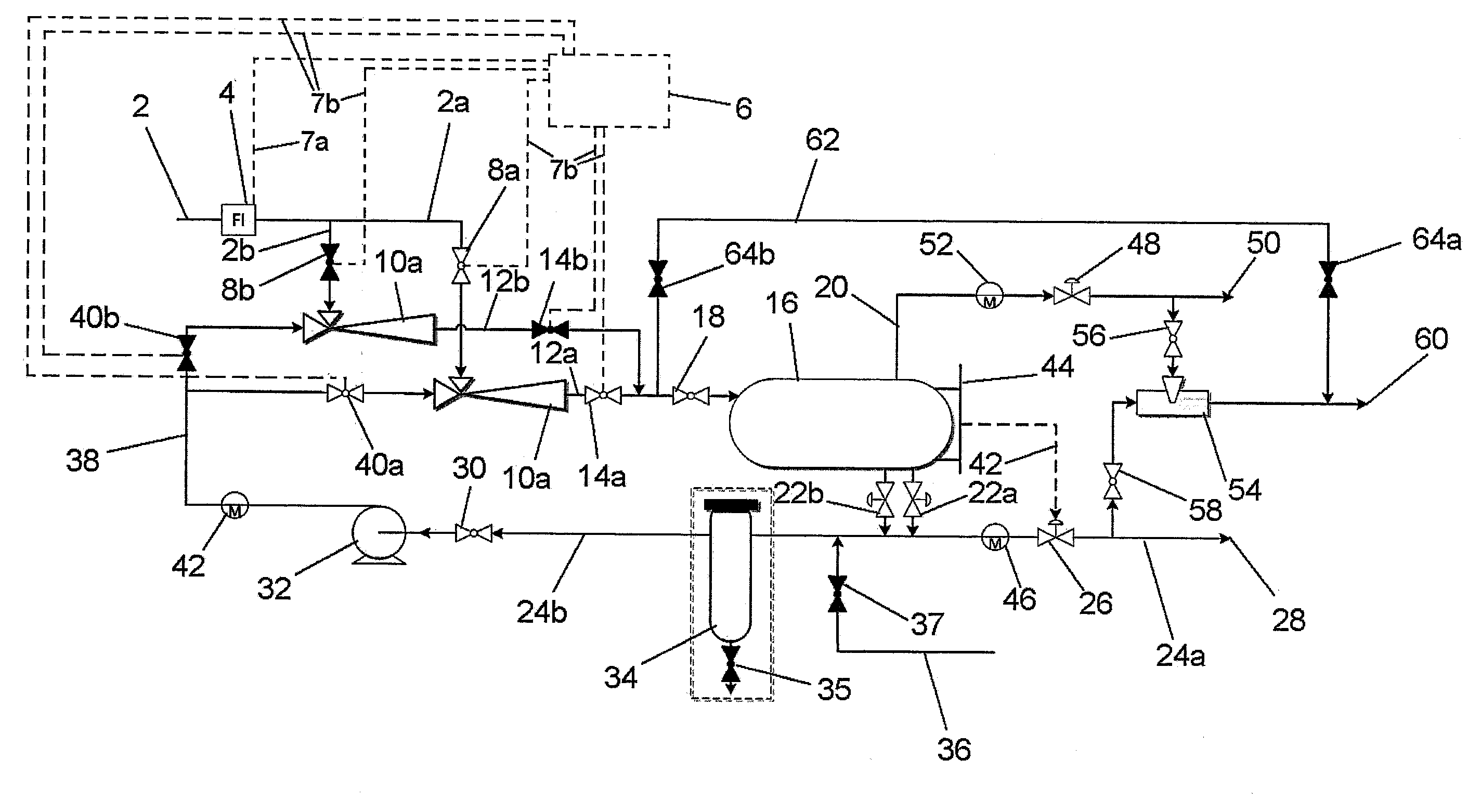
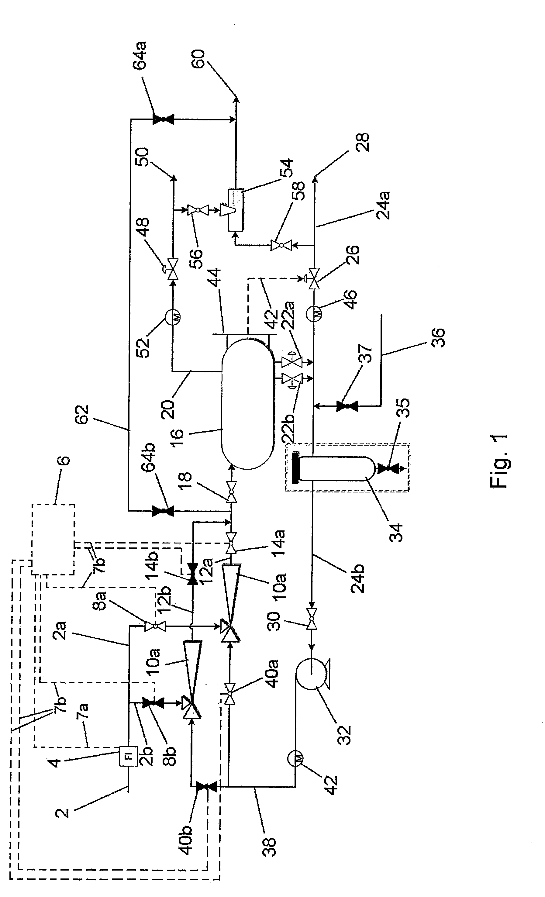
[0044]The system shown in FIG. 1 includes a low pressure (LP) inlet line 2 for LP multiphase fluids (gases and liquids). A flow indicator 4 is fitted into the inlet line 2 to detect the phase of the fluid flowing through the inlet line. The flow indicator 4 provides an output signal to a control device 6 via signal line 7a. The control device 6 and the signal line 7a may be parts of an automatic control system that controls operation of the pressure boosting system via control lines 7b. Alternatively, the control device 6 may include an indicator device that provides an indication of the phase of the fluid flowing through the inlet line 2 and enables an operator to make manual adjustments to control operation of the pressure boosting system.

[0045]Downstream of the flow indicator 4 the inlet line 2 splits into two (or more) branches 2a, 2b, each containing a respective flow control valve 8a, 8b. The flow control valves 8a, 8b may optionally be configured to be controlled automaticall...


PUM

PropertyMeasurementUnit
Pressureaaaaaaaaaa
Flow rateaaaaaaaaaa
Gravityaaaaaaaaaa

Abstract

An apparatus for boosting the pressure of flowing fluids includes a plurality of jet pumps (10a, 10b), each having a LP inlet for LP fluid, a HP inlet for HP liquid and a MP outlet for MP fluid. A fluid separator device (16) is connected to receive the MP fluid from the outlets of the jet pumps, a gas outlet line (20) for a separated gas phase and a liquid outlet (22a, 22b) for separated liquid phase. A liquid return line (24b, 38) is connected to the liquid outlet of the fluid separator device and the HP inlets of the jet pumps (10a, 10b) for returning at least some of the separated liquid phase from the fluid separator device to the HP inlets of the jet pumps, and a mechanical pump (32) is connected into the liquid return line for boosting the pressure of the liquid delivered to the HP inlets of the jet pumps. A flow control system (6) is provided for controlling the flow of fluids through the respective jet pumps (10a, 10b).

Description

CROSS-REFERENCE TO RELATED APPLICATION[0001]This application claims foreign priority under 35 USC 119 to British application no. GB 1504300.3 filed Mar. 13, 2015.FIELD[0002]The present invention relates to an oil / gas production apparatus for boosting the production of oil and gas wells, and in particular to an apparatus for boosting the pressure of flowing fluids produced from oil and gas wells. The invention also relates to a method of increasing the pressure of flowing fluids.BACKGROUND[0003]In order to increase or maintain the production from oil fields with a low production well head pressure (PWHP), a boosting system may be required. Such a system allows the pressure of the extracted gases and liquids to be boosted to the pressure required by downstream processing systems or for transportation by pipeline. If the pressure of these fluids cannot be boosted efficiently, it may be uneconomic to maintain production, or in the case of the multiphase fluids, it may be necessary to fl...

Claims


Application Information

Patent Timeline
IPC IPC(8): E21B43/12F04F5/26F04F5/48E21B43/34
CPCE21B43/124F04F5/48F04F5/26E21B43/34F04F5/10F04F5/24F04F5/54B01D19/0057B01D19/0063E21B43/12E21B43/121F04D31/00B01D1/00
Inventor BEG, MIRZA NAJAM ALI
Owner CALTEC PRODN SOLUTIONS LTD
Why Eureka
Try Eureka