
System and method for delivering a fluid stored in liquefied form to an end user in gaseous form

Active Publication Date: 2016-09-15
WESTPORT FUEL SYST CANADA INC
View PDF5 Cites 13 Cited by
  • Summary
  • Abstract
  • Description
  • Claims
  • Application Information

AI Technical Summary

Benefits of technology

The disclosed system allows for efficient use of fluid by reducing the amount of fluid that is wasted. This is achieved by controlling the predetermined conditions that cause the fluid to be vented to atmosphere. Additionally, the system can detect and prevent contamination in the fluid, which further improves efficiency. A filter can also be used to selectively filter impurities from the fluid before it is returned to the storage vessel. These technical effects make the system more compact, efficient, and effective in use.

Problems solved by technology

While natural gas has been used as a fuel for vehicles for over fifty years, widespread use has been curtailed for various reasons including fuel storage density, infrastructure, availability of fuel, and capital costs that are generally higher compared to conventional liquid-fuelled vehicles.
Because the available space for storing a fuel on board a motor vehicle is often limited, a factor that inhibits broader adoption of natural gas as a transportation fuel has been the energy density of gaseous fuels compared to liquid fuels.
n gas delivery systems that supply fuel to an engine, while natural gas is a naturally occurring constituent of the earth's atmosphere it normally exists in very small amounts and it is both undesirable and wasteful to vent natural gas to atmosphere. A
Heat that leaks into the storage space can cause vaporization of some of the stored fluid, thereby increasing the vapor pressure.
Such solutions add more components and complexity to the system thereby reducing the overall system efficiency and increasing the system's capital and operational cost.
The equipment needed to re-liquefy the fluid is expensive, takes up space, and adds more complexity and weight to the system.

Method used


Image

  • System and method for delivering a fluid stored in liquefied form to an end user in gaseous form
  • System and method for delivering a fluid stored in liquefied form to an end user in gaseous form
  • System and method for delivering a fluid stored in liquefied form to an end user in gaseous form

Examples


Embodiment Construction

)

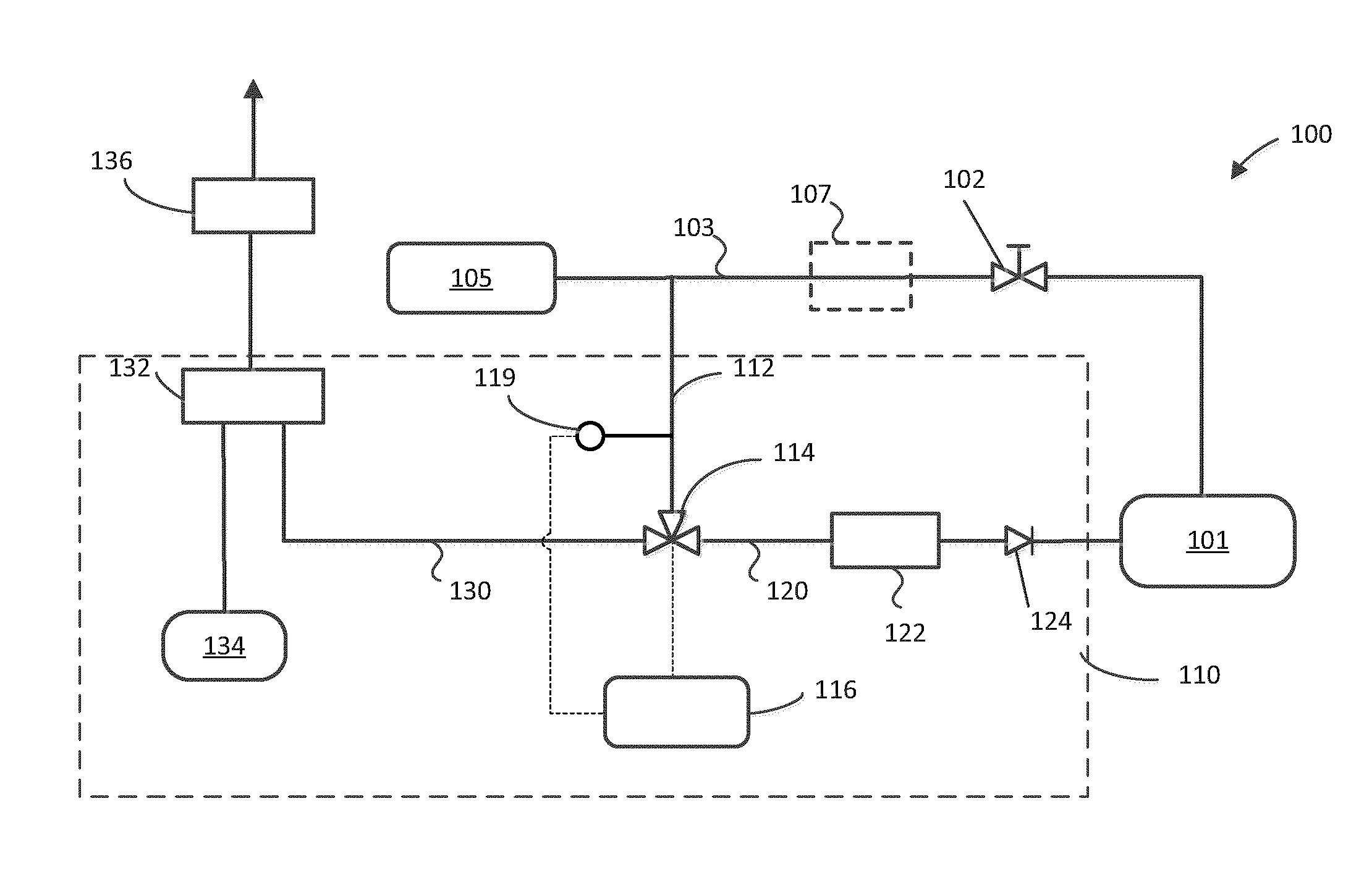
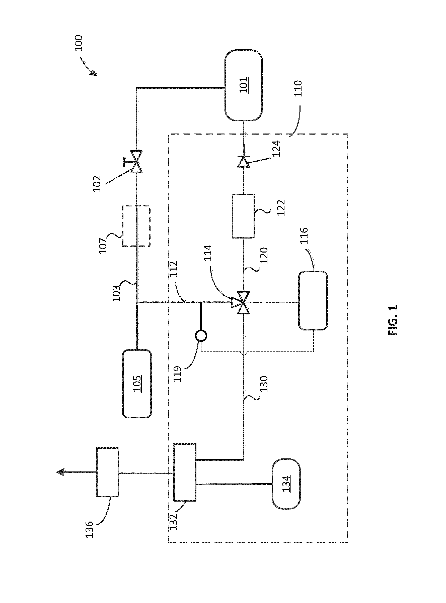
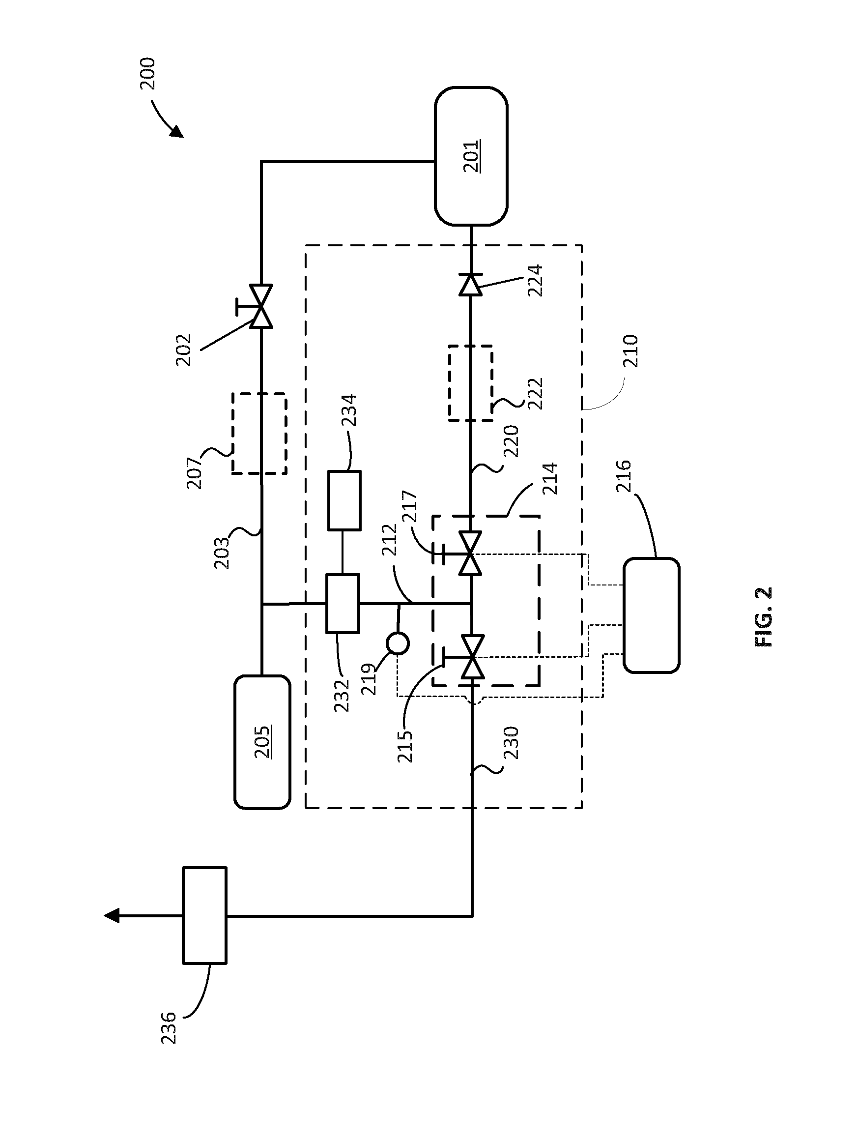
[0028]With reference to the schematic diagram of FIG. 1, system 100 comprises storage vessel 101 for storing a fluid in liquefied form and supply line 103 for delivering fluid in gaseous form to an end user 105. The fluid may be taken from the vapor space of storage vessel 101, already in gaseous form, or it can be warmed and vaporized in optional vaporizer 107, shown in dashed lines, or it can be delivered to the supply line as a supercritical fluid. End user 105 can be an internal combustion engine fuelled with a gaseous fuel as further described in a preferred embodiment or it can be for example a second storage vessel which is filled with gaseous fuel supplied from storage vessel 101. Pressure relief circuit 110 comprises relief line 112 which is fluidly connected to supply line 103 and to switching device 114, which, in the embodiment illustrated in FIG. 1, is a three-way valve. Pressure relief circuit 110 further comprises return line 120 and diversion line 130, which are eac...


PUM


Abstract

A system and method is disclosed for storing a fluid in a storage vessel in liquefied form and delivering it in gaseous form to an end user through a supply line. The system comprises a pressure relief circuit for returning the fluid from the supply line to the vessel when predetermined conditions are met. The pressure relief circuit comprises a return line connected to the supply line and the storage vessel, a diversion line to divert the fluid elsewhere and a switching device operable to direct the fluid to either one of the lines, as a function of predetermined conditions.

Description

FIELD OF THE INVENTION[0001]The present disclosure relates to a system and a method for delivering a fluid stored in liquefied form to an end user in a gaseous form. More particularly, the disclosed system and method are for handling a fluid that is normally in gaseous form at standard pressure and temperature conditions and that is stored in liquefied form in a storage vessel and for returning fluid in gaseous form to the storage vessel when predetermined conditions are met, thereby reducing the amount of fluid that is vented from the system.BACKGROUND OF THE INVENTION[0002]Systems for storing a fluid in liquefied form and delivering the fluid in gaseous form are gaining favor for delivering fuel to internal combustion engines. Internal combustion engines have been used to produce power and drive machines for over a century. Historically, gasoline and diesel have been preferred fuel choices because they were abundant, inexpensive, and easy to store. While natural gas has been used ...

Claims


Application Information

Patent Timeline
IPC IPC(8): F02M21/06F02M21/02F17C9/02
CPCF02M21/06F17C9/02F17C2225/04F02M21/0221F17C2250/03F02M21/0227F17C7/02F17C7/04F17C2205/0326F17C2205/0332F17C2205/0335F17C2205/0347F17C2221/012F17C2221/03F17C2221/033F17C2223/0115F17C2223/0161F17C2223/033F17C2223/035F17C2223/043F17C2223/046F17C2225/0123F17C2225/035F17C2227/0107F17C2227/0393F17C2250/032F17C2260/035F17C2265/066F17C2270/0168Y02E60/32Y02T10/30
Inventor OVERSBY, KEVIN K.
Owner WESTPORT FUEL SYST CANADA INC
Learn More