Portable thermoelectric cooling device for therapeutic craniocervical hypothermia

a cooling device and craniocervical technology, applied in the field of portable thermoelectric cooling devices for craniocervical hypothermia, can solve the problems of inconvenient use, inconvenient use, and inability to carry,

Inactive Publication Date: 2016-09-22
RGT UNIV OF CALIFORNIA
View PDF12 Cites 12 Cited by
  • Summary
  • Abstract
  • Description
  • Claims
  • Application Information

AI Technical Summary

Benefits of technology

[0009]Accordingly, a need exists for a cooling device for therapeutic craniocervical hypothermia which can be specifically directed at the cranial and nec

Problems solved by technology

Unfortunately, most available cooling devices are inefficient or impractical for the implementation of brain hypothermia in emergency situations.
In general, existing cooling devices are burdensome, non-portable, whole body units which do not target the brain specifically.
Cooling is mostly attained after about two hours delay, and many devices interfere with other therapies being performed, such as airway support.
Invasive cooling methods require percutaneous venous access, which inherently carry a risk for complications such as hemorrhage, thrombosis, and infection (local and/or systemic); in general, these devices cannot be readily utilized outside hospital facilities.
A significant limitation of existing external cooling devices is that most of them are massive units that induce cooling to the entire body instead of targeting the brain specifically.
While this type of hypothermia may be beneficial when several or

Method used


Image

  • Portable thermoelectric cooling device for therapeutic craniocervical hypothermia
  • Portable thermoelectric cooling device for therapeutic craniocervical hypothermia
  • Portable thermoelectric cooling device for therapeutic craniocervical hypothermia

Examples


Embodiment Construction

[0025]The therapeutic portable thermoelectric cooling device is designed for the specific treatment of the head and neck in patients with acute neurological emergencies. It is also particularly well-suited for use in domiciliary treatment for individuals with chronic migraines and status epilepticus, and as a replacement for current (less sophisticated) external hypothermia devices in hospital facilities.

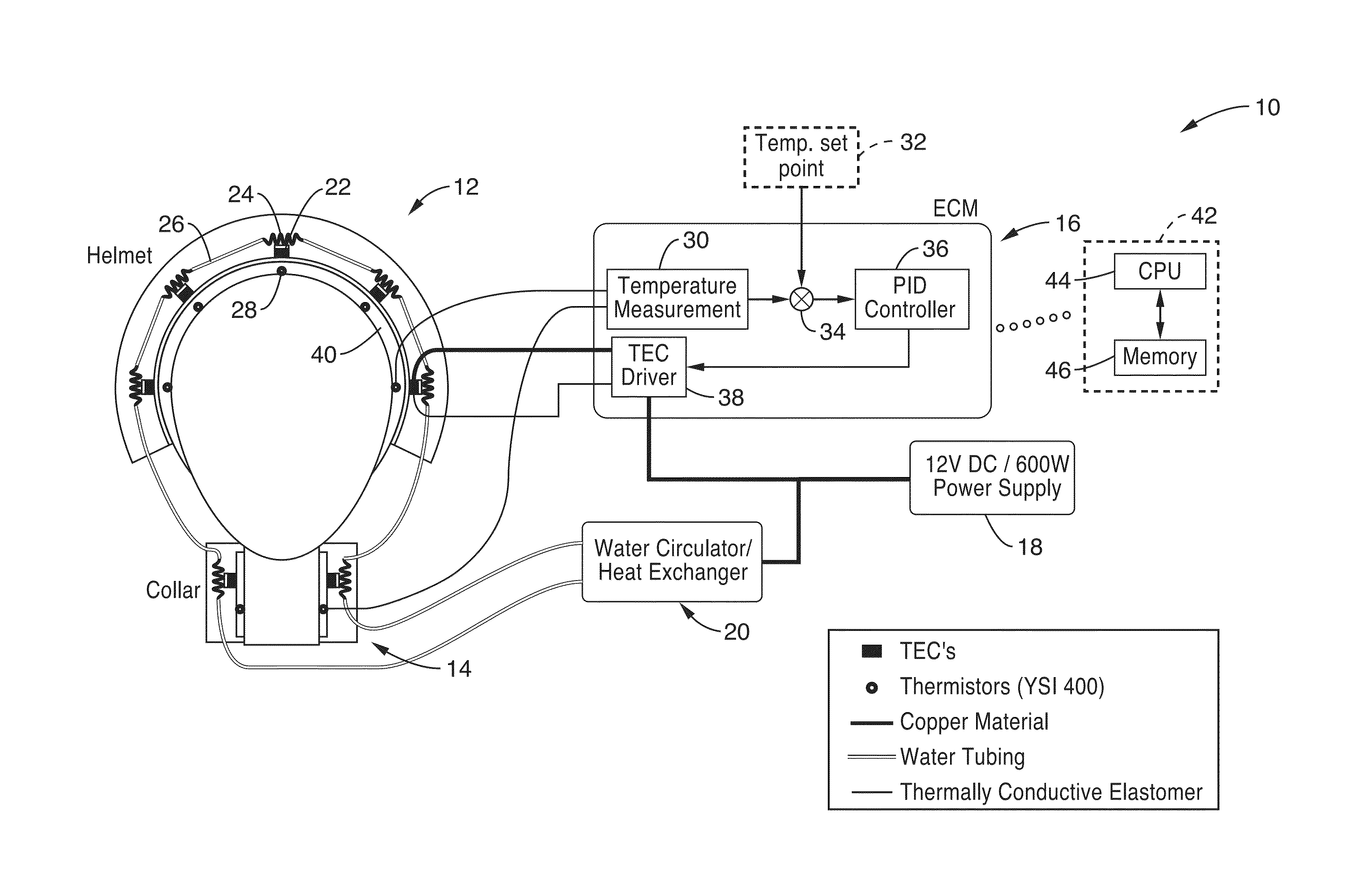
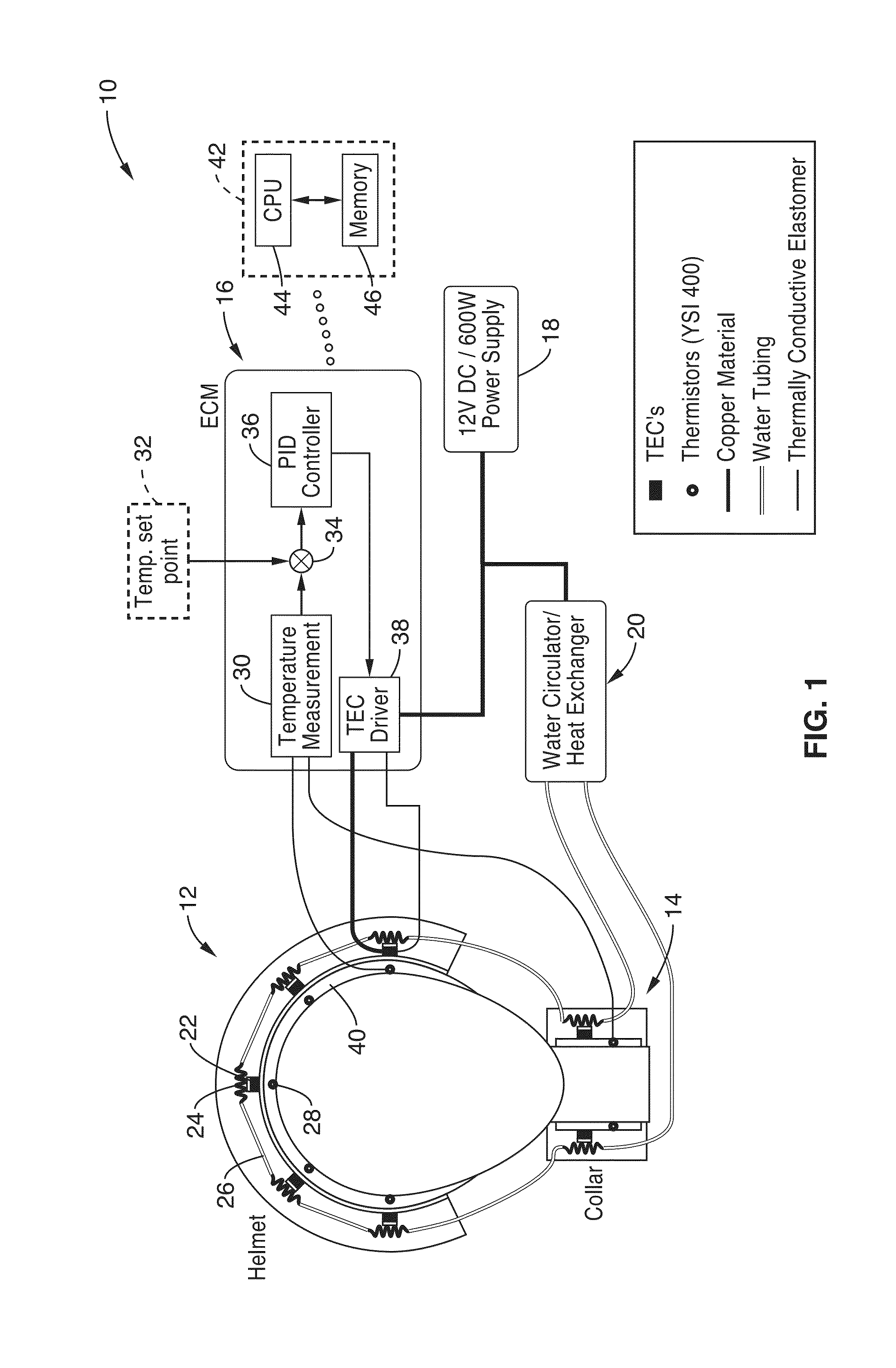
[0026]FIG. 1 illustrates an example embodiment 10 of the inventive portable thermoelectric cooling device. In this embodiment, a cooling and / or heating head gear (helmet) 12 is seen along with a cooling and / or heating neck collar (collar) 14. It should be appreciated that both the helmet and collar are configured as anatomically compliant structures. The helmet 12 and collar 14 are shown coupled to an electronic control module (ECM) 16, a power supply 18 and a combination coolant circulator and heat exchanger 20. In a preferred embodiment, power supply 18 is configured for making th...


PUM


Abstract

A therapeutic craniocervical hypothermia device which provides controlled cooling (heating) through a helmet and collar. The helmet and collar contain a plurality of distributed thermoelectric cooling devices (TECs) distributed on a helmet structure and a liquid coolant system for exchanging heat external to the helmet and collar to keep the TECs operating efficiently. A control circuit drives the TECs in response to measurements from a plurality of temperature sensors held adjacent the patient wearing the helmet and collar. In at least one embodiment, the TECs are grouped within interconnected flexible modules which each contain internal cooling passageways adjacent the TECs.

Description

CROSS-REFERENCE TO RELATED APPLICATIONS[0001]This application is a 35 U.S.C. §111(a) continuation of PCT international application number PCT / US2014 / 057276 filed on Sep. 24, 2014, incorporated herein by reference in its entirety, which claims priority to, and the benefit of, U.S. provisional patent application Ser. No. 61 / 884,932 filed on Sep. 30, 2013, incorporated herein by reference in its entirety. Priority is claimed to each of the foregoing applications.[0002]The above-referenced PCT international application was published as PCT International Publication No. WO 2015 / 048170 on Apr. 2, 2015, which publication is incorporated herein by reference in its entirety.STATEMENT REGARDING FEDERALLY SPONSORED RESEARCH OR DEVELOPMENT[0003]This invention was made with Government support under AR047664 and AR054816, awarded by the National Institutes of Health. The Government has certain rights in the invention.INCORPORATION-BY-REFERENCE OF COMPUTER PROGRAM APPENDIX[0004]Not ApplicableNOTIC...

Claims


Application Information

Patent Timeline
IPC IPC(8): A61F7/00A61F7/02
CPCA61F7/007A61F7/02A61F2007/0096A61F2007/0056A61F2007/0011A61F2007/0002A61F2007/0233A61F2007/0019A61F2007/0029A61F2007/0039A61F2007/0093A61F2007/0071A61F2007/0022A61M19/00A61F2007/0075A61F2007/0078A61F2007/0225A61F2007/0246A61M2210/06A61M16/0627A61M2205/3368A61M2205/3606A61M2205/366A61M2205/505A61M2205/8206A61M2205/8262A61F2007/0296A61F2007/0076
Inventor VERGARA, JULIO L.SERRANO CARMONA, RAULRESTREPO, LUCAS
Owner RGT UNIV OF CALIFORNIA
Why Eureka
Try Eureka