LED spherical lamp

a technology of led spherical lamps and led spherical lamps, which is applied in the direction of semiconductor devices for light sources, coupling device connections, lighting and heating apparatus, etc., can solve the problems of increased manufacturing time and cost, inconvenient new set of positive and negative terminals, and inconvenient use of conventional led spherical lamps, etc., to achieve good electrical conduction of power supply units, prevent poor contacts, and simplify the overall assembly and manufacturing procedure

Active Publication Date: 2016-09-22
EPISTAR CORP
View PDF1 Cites 4 Cited by
  • Summary
  • Abstract
  • Description
  • Claims
  • Application Information

AI Technical Summary

Benefits of technology

[0011]In addition, the electrical connector further includes a pair of limit portions disposed opposite to an outer side of the electrical connector, and a side of each limit portion has a plurality of second latch slots corresponsive to the second pin terminals and provided for fixing the second pin terminals respectively, and the other side of each limit portion abuts a plane of the substrate when the electrical connector is installed to the substrate, so as to achieve the position limiting effect.
[0012]In summation, the LED spherical lamp of the present invention not just simplifies the overall assembling and manufacturing procedure of the lamp only, but also assures a good electrical conduction of the power supply unit with the substrate and the LED light emitting elements through the electrical connector, prevents poor contacts, and provides a simple, easy and quick replacement for damaged components or electric driving problems.

Problems solved by technology

In order to receive power, the LED light emitting elements require the aforementioned step in the assembling process, and thus not just incurring greater manufacturing time and cost only, but also having an issue of disconnecting the positive and negative terminals from a conductive circuit easily and affecting the operation of the LED light emitting elements.
When a related component such as the substrate, the LED light emitting elements and the power supply unit are damaged, it is necessary to remove all components before replacing the damaged component.
Obviously, the conventional LED spherical lamps are inconvenient.
Particularly, when the power supply unit is damaged, anew set of positive and negative terminals is required.

Method used


Image

  • LED spherical lamp
  • LED spherical lamp
  • LED spherical lamp

Examples


Embodiment Construction

[0018]The technical content of the present invention will become apparent with the detailed description of preferred embodiments and the illustration of related drawings as follows.

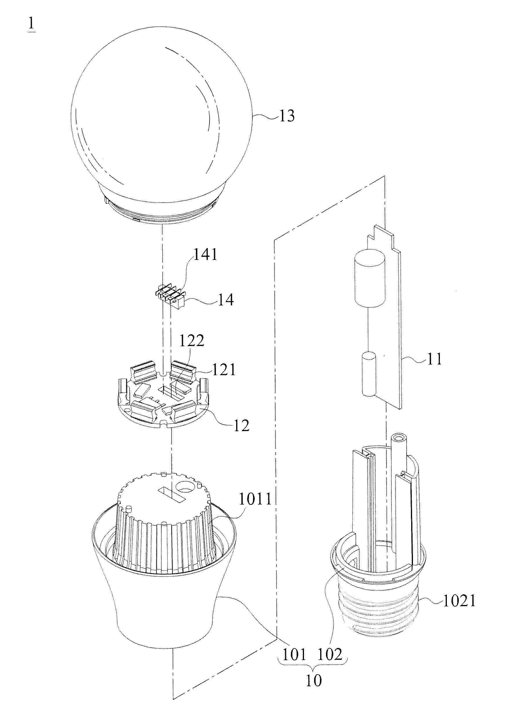
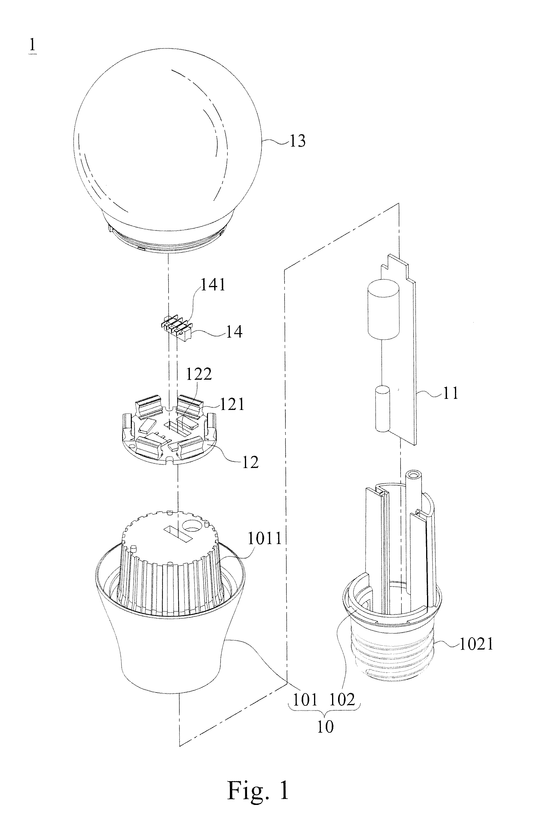
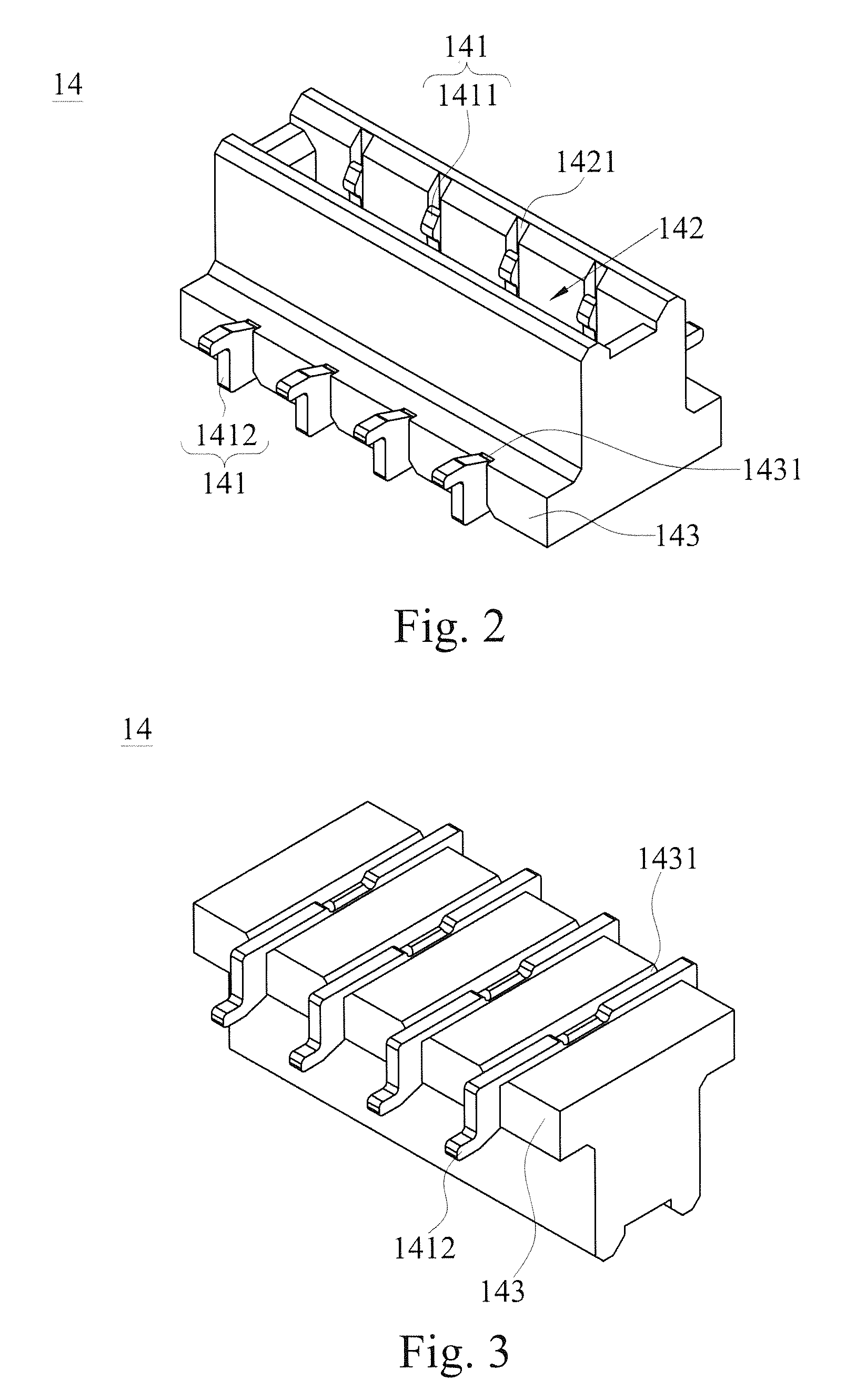
[0019]With reference to FIGS. 1, 2-3 and 4A-4B for the exploded view, the first and second perspective views of an electrical connector, the cross-sectional view of assembling an LED spherical lamp, and the partial blowup view of the LED spherical lamp in accordance with a preferred embodiment of the present invention respectively, the LED spherical lamp 1 comprises a base 10 for installing an power supply unit 11, a substrate 12 and a cover 13 therein, and the power supply unit 11 is installed inside the base 10, and the substrate 12 includes a plurality of LED light emitting elements 121 and is coupled to aside of the base 10, and the cover 13 is fixed to the base 10 for covering the substrate 12. Wherein, the base 10 has a first carrying portion 101 and a second carrying portion 102 engaged with each o...


PUM


Abstract

An LED spherical lamp includes a base, a power supply unit, a substrate and a cover. The power supply unit is installed inside the base, and the substrate has plural LED light emitting elements and is coupled to a side of the base, and the cover is fixed to the base for covering the substrate. The LED spherical lamp includes an electrical connector installed to the substrate and having a plurality of electrical terminals for electrically connecting the substrate to the power supply unit, and an engaging slot is concavely formed on a side of the electrical connector, such that the power supply unit drives the LED light emitting elements to achieve the lighting effect. The LED spherical lamp has the effects of simplifying the assembling and manufacturing procedure, assuring the electrical conduction of components, and facilitating the maintenance, repair, and replacement of the components.

Description

CROSS-REFERENCE TO RELATED APPLICATIONS[0001]This non-provisional application claims priority under 35 U.S.C. §119(a) on Patent Application No(s). 104204194 filed in Taiwan, R.O.C. on Mar. 20, 2015, the entire contents of which are hereby incorporated by reference.BACKGROUND OF THE INVENTION[0002]1. Field of the Invention[0003]The present invention relates to the field of LED lamps, and more particularly to an LED spherical lamp having the features of simple manufacturing process, easy installation, excellent electrically conductive status, and easy maintenance.[0004]2. Description of the Related Art[0005]At present, most lights and lamps use light emitting diodes (LEDs) as a primary light source, and various types of lamps such as ceiling lights, down lamps, ceiling lamps and spherical lamps are available for different lighting effects and purposes and used extensively in daily life.[0006]Among the spherical lamps, LED spherical lamps with the advantages of environmental protection...

Claims


Application Information

Patent Timeline
Patent Type & Authority Applications(United States)
IPC IPC(8): F21K99/00F21V23/06F21V23/02F21K9/232F21K9/238F21Y115/10
CPCF21K9/135F21Y2101/02F21V23/06F21V23/023F21V23/006F21K9/232F21Y2115/10H01R33/7642H01R33/9453F21K9/238F21K9/278F21V23/003F21V23/004
Inventor WU, CHIH-HSIENTSAI, SEN-YUHHUANG, CHUN-CHIEHCHEN, YU-CHANG
Owner EPISTAR CORP
Why Eureka
Try Eureka