Optical data center network system and optical switch

a network system and optical switch technology, applied in the field of network systems, can solve the problems of high bandwidth and low latency for data transmission, large amount of east-west server-to-server traffic within dcns, and still limited transmission rate of electrical switches, so as to achieve high bandwidth and low latency, high reliability, and high reliability

Active Publication Date: 2016-09-22
GENOPSYS TECH INC
View PDF6 Cites 68 Cited by
  • Summary
  • Abstract
  • Description
  • Claims
  • Application Information

AI Technical Summary

Benefits of technology

[0010]The disclosure is directed to an optical data center network system and an optical switch, which feature

Problems solved by technology

Evidence shows that these applications/services not only involve much client-server (i.e., north-south) traffic flowing in and out within DCNs, but also spawn a massive amount of east-west server-to-server traffic within DCNs.
These applications and services are data rich by nature, and demand high bandwidth and low latency transport of data.
Although the DCN architectures applying the electrical switch adopt optical fibers to transmit data between the switches, a transmission rate thereof is still limited by the electrical switch.
Moreover, during a data transmission process, a photoelectric converter has to be used to implement multiple optical-to-electrical conversions or electrical-to-optical conversions, which causes a large power consumption.
Moreover, since the number of input/output ports of the electrical switch is limited, and one optical fiber can only contain one wavelength band, the number of cables used for network connection is huge, which greatly increases a degree of difficulty in deployment and maintenance, and accordingly increases difficulty in network expansion.
The photoelectric mixed architecture still has the problem of electrical-to-optical conversion, so that the problem in power consumption is not effectively resolved.
For example, in a double tier annular wavelength division multiplexing (WDM) optical data center network architecture, only two no

Method used


Image

  • Optical data center network system and optical switch
  • Optical data center network system and optical switch
  • Optical data center network system and optical switch

Examples


Embodiment Construction

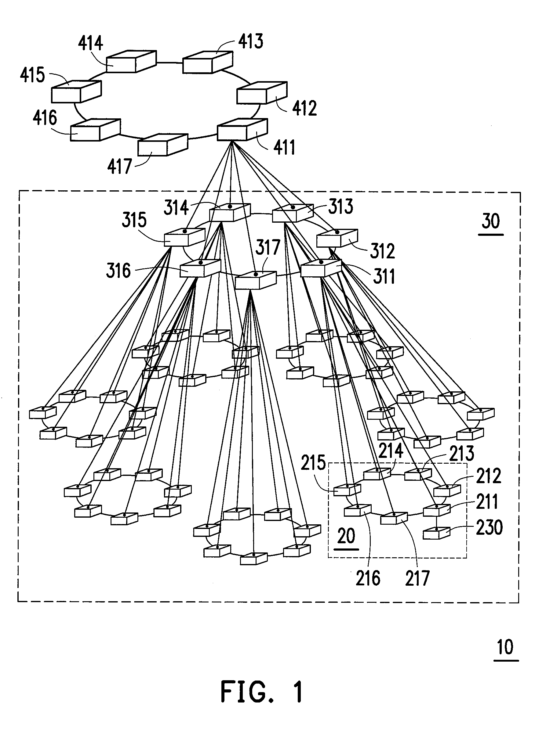
[0027]Although current data center networks (DCNs) employ optical transmission, electrical switches are still used to switch packets, for example, top of rack (ToR) switches, aggregation switches and core switches, etc. These electrical switches are generally connected to each other in two kinds of architectures: a scale-up architecture and a scale-out architecture.

[0028]The scale-up architecture adopts a hierarchical structure in which the switches at higher level of hierarchy have higher capacity and more connection ports to meet an increasing traffic demand. In order to ensure sustainable scalability, the scale-up architecture adopts oversubscription between tiers, such that the bisection bandwidth offered can be less than the worst-case aggregate bandwidth. The scale-up architecture is quite efficient in short term, however a lot of problems may still be caused by a poor modularity capability, gradually increased latency and latency variation.

[0029]On the other hand, in the scal...


PUM


Abstract

An optical data center network system including multiple tier-1 optical switches, multiple tier-2 optical switches and multiple tier-3 optical switches is provided. A pod is formed by the tier-1 optical switches connected to each other through ribbon fibers. A macro pod is formed by the tier-2 optical switches connected to each other through ribbon fibers, and each of the tier-2 optical switches is connected to all of the tier-1 optical switches in one pod. The tier-3 optical switches are connected to each other through ribbon fibers, and each of the tier-3 optical switches is connected to all of the tier-2 optical switches in one macro pod. Each optical switch in each tier is implemented by using the Wavelength Selective Switch (WSS) as a basic element, which has been commercialized numerously.

Description

CROSS-REFERENCE TO RELATED APPLICATION[0001]This application claims the priority benefit of Taiwan application serial no. 104108991, filed on Mar. 20, 2015. The entirety of the above-mentioned patent application is hereby incorporated by reference herein and made a part of this specification.BACKGROUND[0002]1. Field of the Disclosure[0003]The disclosure relates to a network system, and particularly relates to an optical data center network system and an optical switch.[0004]2. Description of Related Art[0005]Data center networks (DCNs) have been designed to provide reliable and efficient network infrastructure for a data center to support a wide variety of today's cloud or enterprise applications and services, e.g., grid / cloud computing, data storage, data mining and social networking, etc. Evidence shows that these applications / services not only involve much client-server (i.e., north-south) traffic flowing in and out within DCNs, but also spawn a massive amount of east-west server...

Claims


Application Information

Patent Timeline
IPC IPC(8): H04Q11/00H04J14/02G02B6/293G02B6/35G02B6/44
CPCH04Q11/0005G02B6/3556G02B6/4404H04Q2011/0016G02B6/29386H04J14/0212G02B6/356G02B6/00
Inventor YUANG, MARIA C.TIEN, PO-LUNGCHEN, HSING-YU
Owner GENOPSYS TECH INC
Why Eureka
Try Eureka