Two-phase cooling with ambient cooled condensor

Active Publication Date: 2016-09-22
IBM CORP
View PDF6 Cites 10 Cited by
  • Summary
  • Abstract
  • Description
  • Claims
  • Application Information

AI Technical Summary

Benefits of technology

[0024]According to a further embodiment of the disclosure, the method includes minimizing a flow rate of the liquid coola

Problems solved by technology

Current cooling methods are not suitable for microprocessors wit

Method used


Image

  • Two-phase cooling with ambient cooled condensor
  • Two-phase cooling with ambient cooled condensor
  • Two-phase cooling with ambient cooled condensor

Examples


Embodiment Construction

[0029]Exemplary embodiments of the disclosure as described herein generally include two phase cooling systems for microprocessors. Accordingly, while embodiments of the disclosure are susceptible to various modifications and alternative forms, specific embodiments thereof are shown by way of example in the drawings and will herein be described in detail. It should be understood, however, that there is no intent to limit embodiments of the disclosure to the particular exemplary embodiments disclosed, but on the contrary, embodiments of the disclosure cover all modifications, equivalents, and alternatives falling within the spirit and scope of the disclosure.

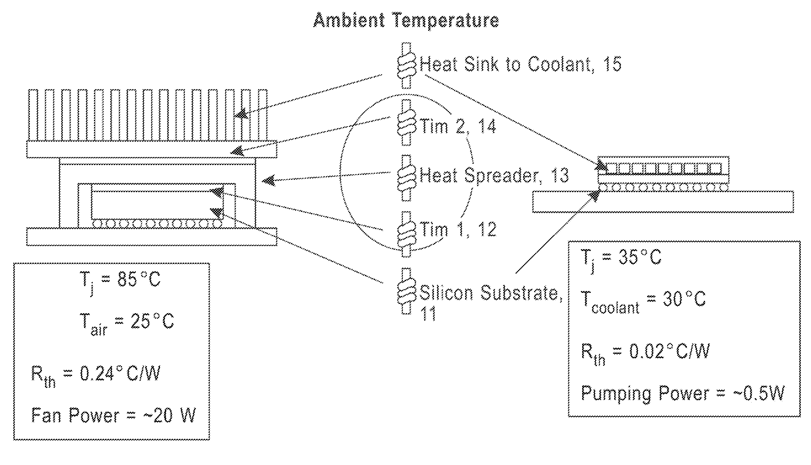
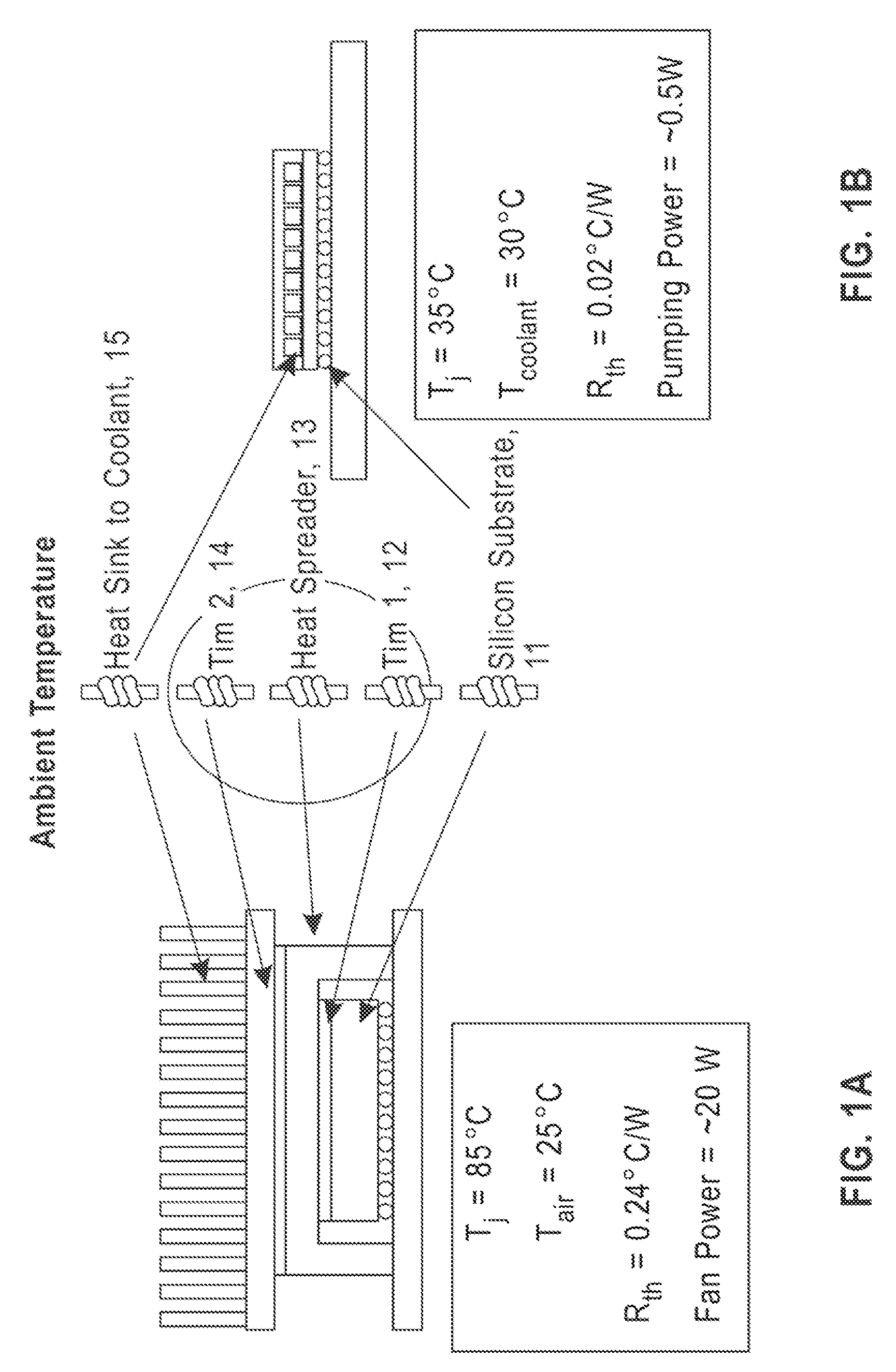
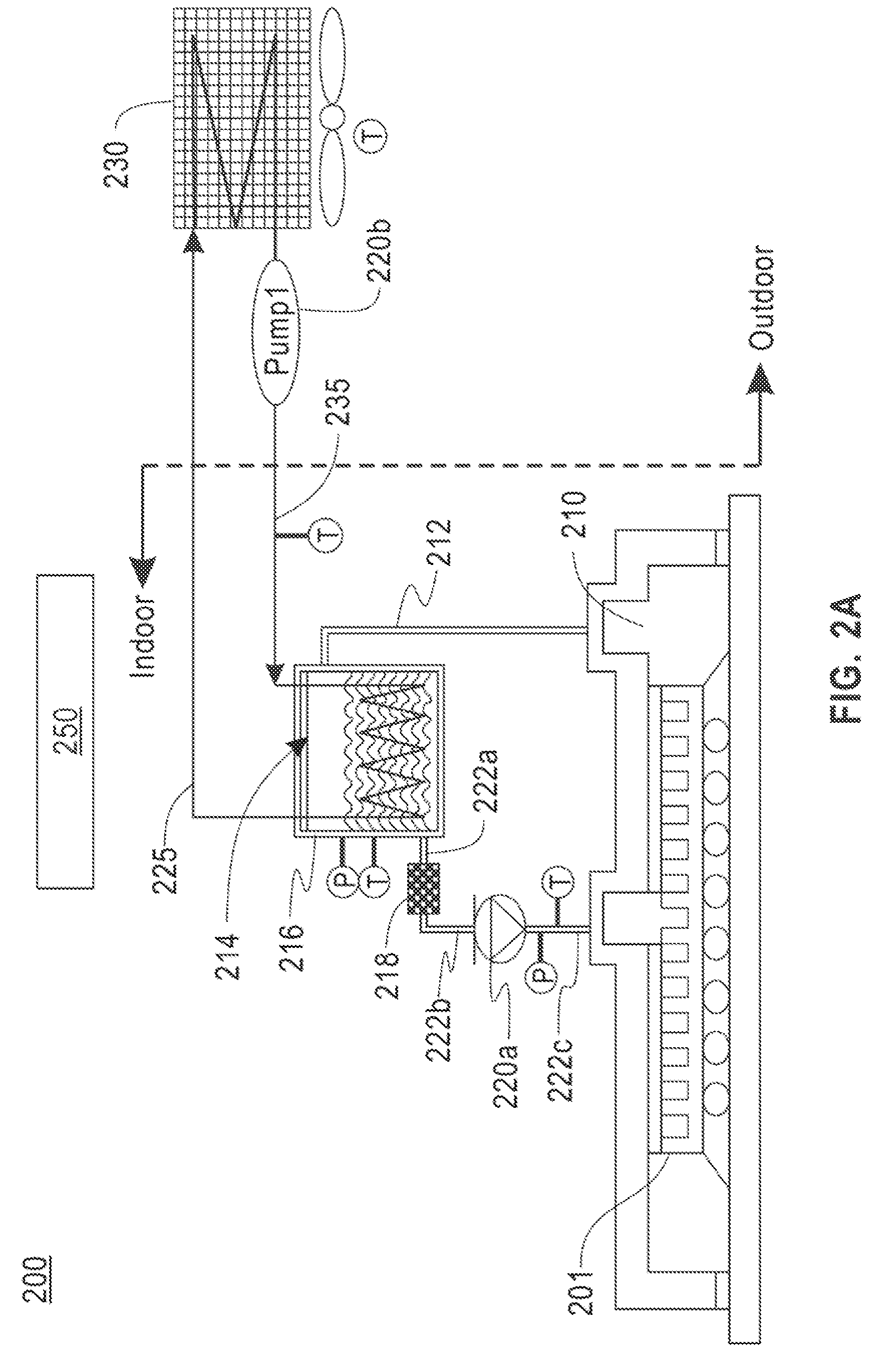
[0030]Embodiments of the present disclosure can realize thermal improvements over the baseline air cooled systems by deploying an intrachip two-phase evaporative cooling to minimize thermal resistance and achieve a lower temperature gradient between the chip junction and the local refrigerant temperature. An exemplary, non-limitin...


PUM


Abstract

An apparatus for cooling a computer system includes a primary cooling loop. The primary cooling loop includes an evaporator configured to cool at least a component of the computer system, an ambient cooled condenser connected to the evaporator, a first pump to provide a coolant flow within the cooling loop, a pressure regulator configured to maintain a selected pressure in the primary cooling loop, and a controller responsive to changes in outdoor ambient conditions and an amount of heat dissipated by the computer system and configured to dynamically adjust the pump and pressure regulator in response thereto.

Description

BACKGROUND[0001]1. Technical Field[0002]Embodiments of the present disclosure are directed to cooling systems for semi-conductor electronic devices such as computer processors.[0003]2. Discussion of the Related Art[0004]The application of two phase cooling for embedded cooling of microprocessors may improve computational efficiency by reducing the total power usage of a computer system. Current cooling methods are not suitable for microprocessors with a high heat flux or for cooling 3-dimensional (3D) chip stacks.SUMMARY[0005]According to an embodiment of the disclosure, there is provided an apparatus for cooling a computer system that includes a primary cooling loop. The primary cooling loop includes an evaporator configured to cool at least a component of the computer system, an ambient cooled condenser connected to the evaporator, a first pump to provide a coolant flow within the cooling loop, a pressure regulator configured to maintain a selected pressure in the primary cooling ...

Claims


Application Information

Patent Timeline
IPC IPC(8): H05K7/20
CPCH05K7/20354H05K7/20309H05K7/20318H05K7/20809H01L23/34H01L23/427G06F1/206G06F2200/201Y02D10/00F25B39/04F25B2339/04F25B2339/044H05K7/20327H05K7/2029F25B2600/2513F25B2700/2106F25B2600/13F25B2700/21172F25B2700/21175F25B2600/2515
Inventor CHAINER, TIMOTHY J.DAVID, MILNES P.PARIDA, PRITISH R.
Owner IBM CORP
Why Eureka
Try Eureka