
Spectroscopic Sensor for Thickness or Weight Measurement of Thin Plastic Films

a technology of thin film and spectroscopic sensor, which is applied in the direction of interferometric spectrometry, instruments, weighing apparatus using radiation, etc., can solve the problems of not providing adequate spectral range, compact spectrometer providing high spectral range and resolution, and reducing the sensitivity of the radiation receiver to selected components within the layer. , to achieve the effect of enhancing the sensitivity of the radiation receiver

Active Publication Date: 2016-09-29
HONEYWELL INC
View PDF5 Cites 17 Cited by
  • Summary
  • Abstract
  • Description
  • Claims
  • Application Information

AI Technical Summary

Benefits of technology

The patent describes a device that uses a layer of material to measure a property. The device has a measurement cell made up of plates that reflect the radiation multiple times before it is detected. The plates scatter the light in a way that makes it difficult to determine the angle at which the light enters the plate. This scattering pattern, known as Lambertian scattering, enhances the sensitivity of the device to certain components in the layer. The technical effect is the improvement of sensitivity in measuring properties of a layer of material using a device with a layer of material and a measurement cell.

Problems solved by technology

However, these sensor attributes are usually mutually exclusive.
For example, a single detector and filter combination affords high signal-to-noise ratio and potentially good spectral resolution but does not provide adequate spectral range.
Conversely, a compact spectrometer provides high spectral range and resolution but sacrifices throughput.
Additionally, while spectrometers provide high spectral range and resolution, a single unit does not cover the entire range between the visible and mid-IR due to practical and technical considerations.

Method used


Image

  • Spectroscopic Sensor for Thickness or Weight Measurement of Thin Plastic Films
  • Spectroscopic Sensor for Thickness or Weight Measurement of Thin Plastic Films
  • Spectroscopic Sensor for Thickness or Weight Measurement of Thin Plastic Films

Examples


Embodiment Construction

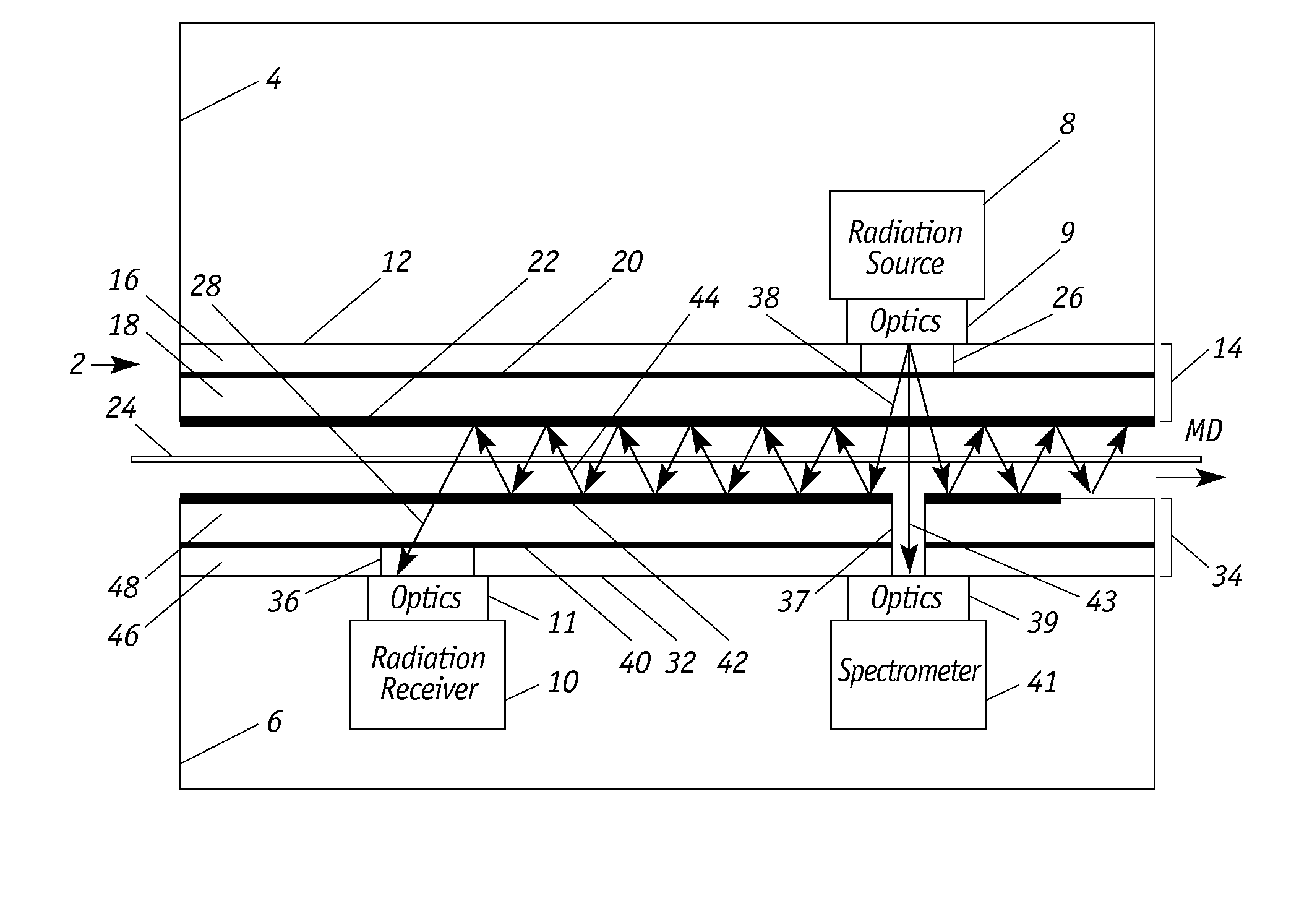
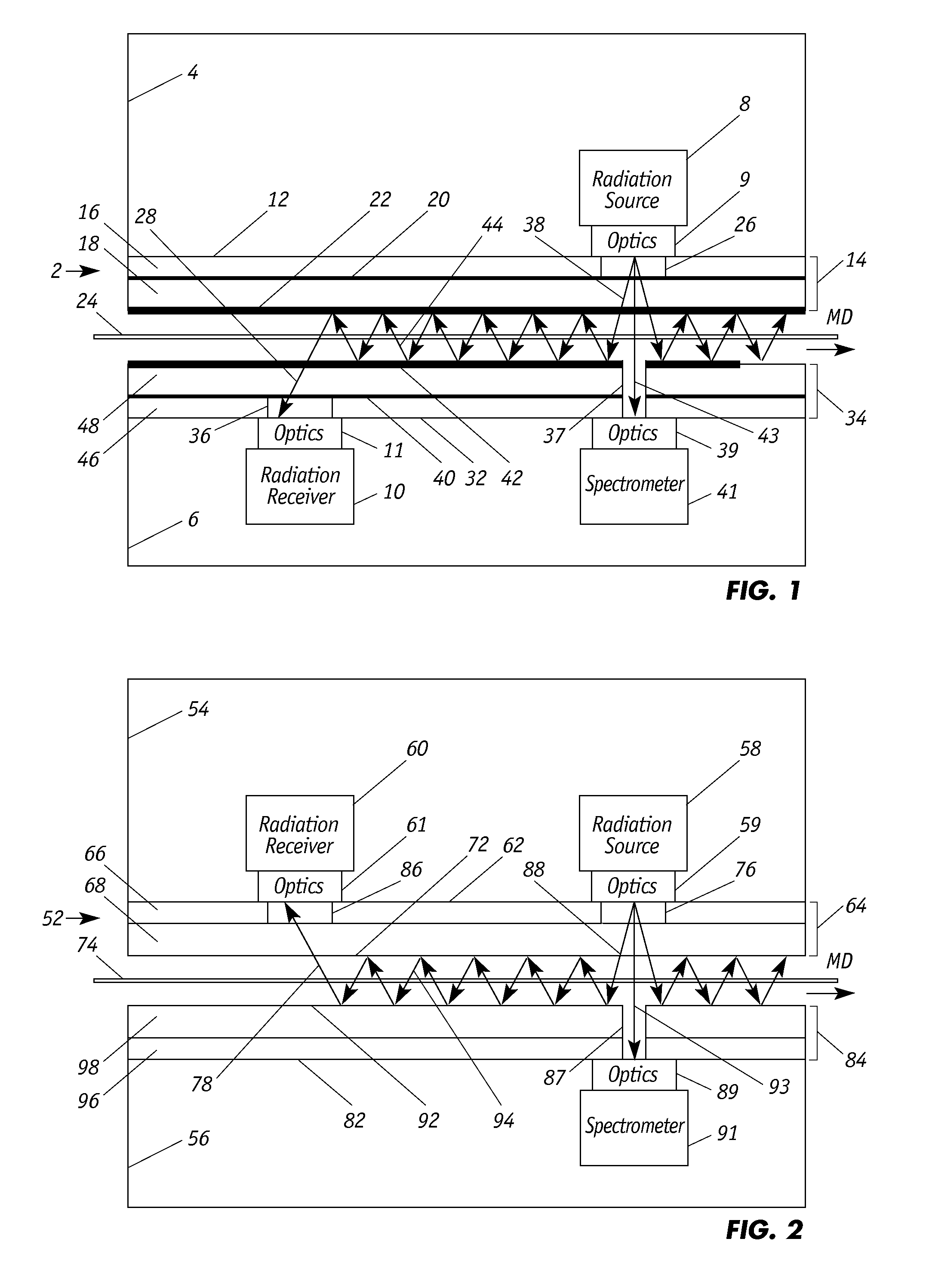
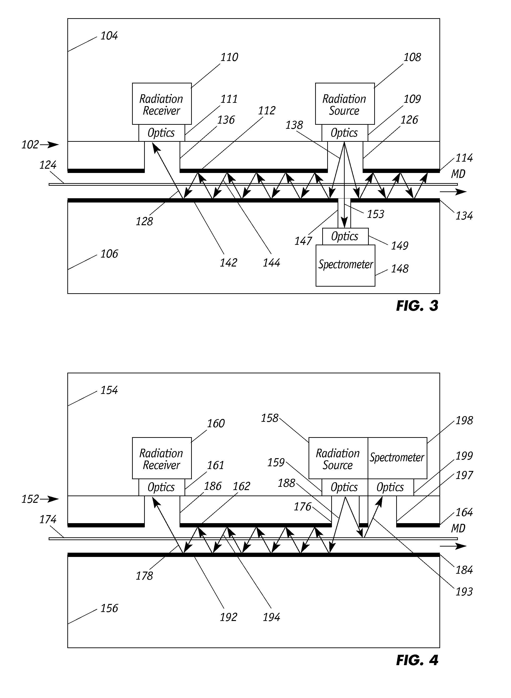
[0022]FIG. 1 illustrates a non-contacting optical sensor 2 that includes enclosures 4 and 6 (each also called “scanner head” or “head”) that house sensor components for measuring qualities, characteristics or features of a moving web 24 that can be monitored which include, but are not limited, to single and multi-layered compositions, coatings, films, webs or sheets. While the sensor will be illustrated in measuring characteristics in paper and plastic, it is understood that the sensor can be employed to detect a variety of components in a number of different materials including, for example, coated materials, fabrics, and the like. Sensor 2 is particularly suited for measuring the thickness or weight of a layer of light transmissive material 24 moving in the machine direction (MD). Scanner 2 includes a radiation or light source 8 that is positioned in head 4 and spectrometer 41 and a radiation receiver or detector 10 that are both positioned in head 6. An upper diffuse reflector pl...


PUM

PropertyMeasurementUnit
thicknessesaaaaaaaaaa
anglesaaaaaaaaaa
thicknessaaaaaaaaaa

Abstract

Continuous on-line thin film measurements employ a sensor having a spectrometer for interferometric measurements and a stack of single channel detectors for adsorption measurements. The stack is separated from the spectrometer, which analyzes radiation that emerges (transmitted pass or reflected from) the film, whereas the stack analyzes radiation that has passed through the film multiple times. The spectrometer is (i) positioned directly opposite the source of radiation so that it detects transmitted radiation or (ii) disposed on the same side of the film as is the source of radiation so that the spectrometer detects radiation that is specularly reflected from the film. The sensor includes a broadband radiation source emitting visible to far infrared light which propagates through a measurement cell defined by reflective surfaces exhibiting Lambertian-type scattering. The sensor is capable of measuring thin plastic films with thicknesses down to 1 micron or less.

Description

FIELD OF THE INVENTION[0001]The present invention generally relates to sensors for measuring thin films using a combination of interferometry and near infrared absorption at fixed wavelengths.BACKGROUND OF THE INVENTION[0002]In the manufacture of sheet materials, it is well known that various sheet properties can be detected “on-line,” that is, while a sheet making machine is operating. On-line measurement devices measure sheet properties such as thickness, basis weight, moisture content, chemical composition and the like. Typically, such on-line devices employ sensors that periodically traverse, or scan, the moving sheets in the cross direction, which is perpendicular to the machine direction of sheet travel.[0003]Visible, near-IR and mid-IR sensors share a common need for large spectral range, high spectral resolution and high signal-to-noise ratio. A large spectral range is needed for the sensor to address a wide number of applications whereas high spectral resolution and signal-...

Claims


Application Information

Patent Timeline
Patent Type & Authority Applications(United States)
IPC IPC(8): G01N21/84G01J3/45G01N21/3563G01B11/06G01G9/00
CPCG01N21/8422G01B11/0675G01G9/00G01N2201/061G01J3/45G01N2021/8427G01N2201/068G01N21/3563G01G9/005G01N21/031G01N21/31G01N21/86G01N2021/3155G01N2021/8609G01N21/3559G01B11/0625
Inventor TIXIER, SEBASTIENHARAN, FRANK MARTIN
Owner HONEYWELL INC
Learn More