Device for the contactless charging of an electrical energy storage means of a motor vehicle

a technology for electrical energy storage and motor vehicles, which is applied in the direction of charging stations, electric vehicle charging technology, transportation and packaging, etc., can solve the problems of affecting the service life the damage of vandalism in the vicinity of the charging station, and the wear of the user, so as to prevent damage

Active Publication Date: 2016-10-06
DR ING H C F PORSCHE AG
View PDF7 Cites 7 Cited by
  • Summary
  • Abstract
  • Description
  • Claims
  • Application Information

AI Technical Summary

Benefits of technology

[0016]A device according to the invention for the contactless charging of an electrical energy storage of a motor vehicle is distinguished by the fact that the at least one primary coil is connected to the bottom housing in such a way as to yield mechanically under the effect of an external compressive force. The invention is based on the idea of connecting the primary coil to the bottom housing not in a rigid manner but in a yielding manner. Avoiding a rigid connection of the primary coil to the bottom housing makes it possible to counteract the problem of a motor vehicle with a height-adjustable chassis that has an air suspension device setting down on the primary coil in such a way that damage may result, if for example the air suspension device sags owing to its time in service. The sagging of the air suspension device causes a pressure to be exerted on the primary coil from above. However, according to the invention, the primary coil is connected to the bottom housing in a yielding manner and is pressed down, so that damage is prevented.
[0018]The at least one compression spring means may extend between a bottom of the bottom housing and the primary coil. The spring force of the compression spring means consequently precisely counteracts the force of the weight of the motor vehicle.
[0019]The at least one compression spring may be a helical spring. This allows the at least one compression spring to be mechanically robust.
[0022]The length of the at least one compression spring means may be chosen so that, in the unloaded state, the primary coil is kept at a distance from the secondary coil in such a way that an air gap forms between the primary coil and the secondary coil at a lower height level of a height-adjustable chassis of the motor vehicle that has at least two height levels. This measure achieves the effect that the air gap between the primary coil and the secondary coil can be adjusted reliably by lowering the height-adjustable chassis.
[0024]The bottom housing may have an overall height that is chosen so that setting down of the motor vehicle on an upper side of the bottom housing can be prevented in the event of sagging of the motor vehicle. Thus, even in the event of sagging of an air suspension device of a height-adjustable chassis of the motor vehicle owing to its service life, the primary coil yields but the motor vehicle nevertheless will not set down on an upper side of the bottom housing.

Problems solved by technology

The charging operation on the public power supply system always requires intervention by the vehicle user, since the charging cable has to be inserted into the charging interfaces provided for it, as a result of which they are subject to wear.
Charging of the electrical energy storage of the motor vehicle is not possible if the vehicle user inadvertently leaves the charging cable behind.
Charging stations in areas that are accessible to the public often are damaged by vandalism.
The air suspension device on a motor vehicle that has been in service for a relatively long time may sag.
Sagging of the air suspension device may cause the motor vehicle to set down on the primary coil and may cause damage to the coils.
Thus, even in the event of sagging of an air suspension device of a height-adjustable chassis of the motor vehicle owing to its service life, the primary coil yields but the motor vehicle nevertheless will not set down on an upper side of the bottom housing.

Method used


Image

  • Device for the contactless charging of an electrical energy storage means of a motor vehicle
  • Device for the contactless charging of an electrical energy storage means of a motor vehicle

Examples


Embodiment Construction

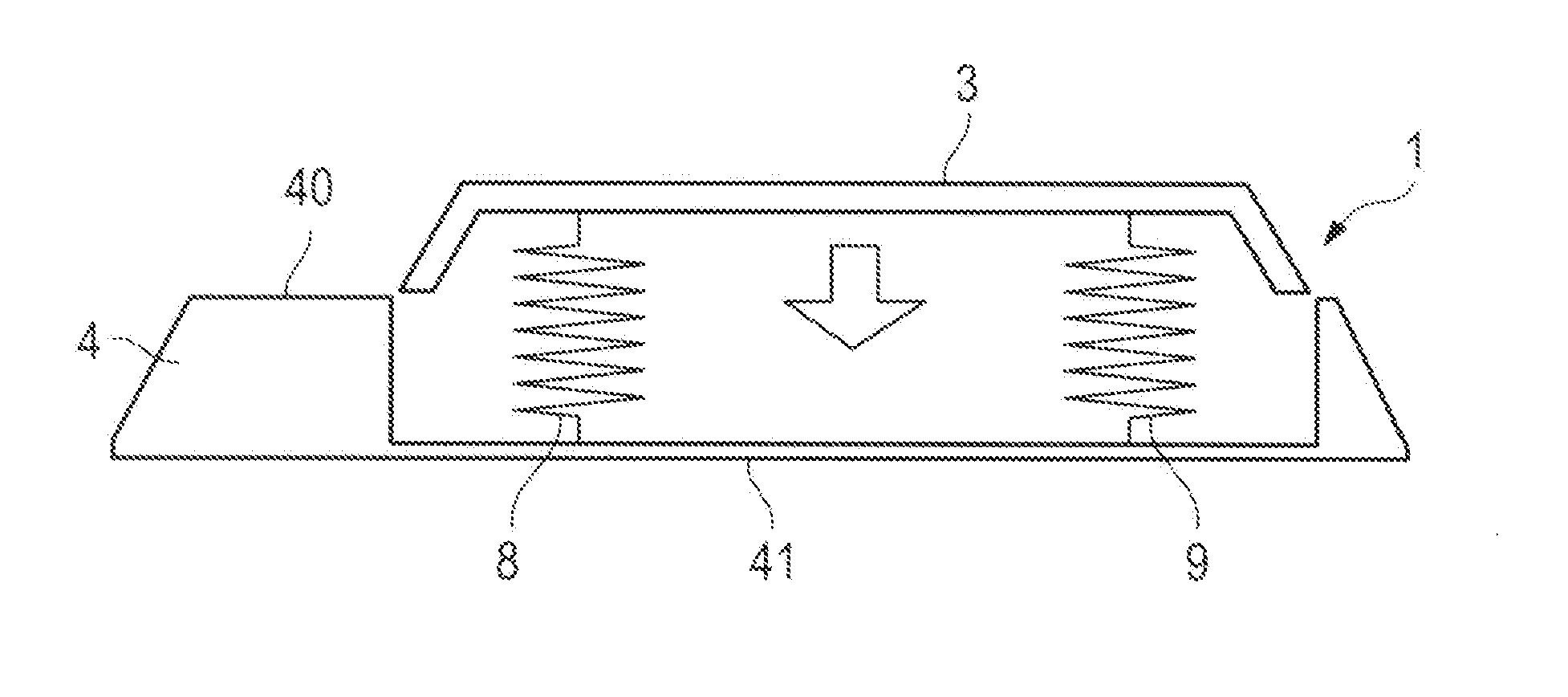
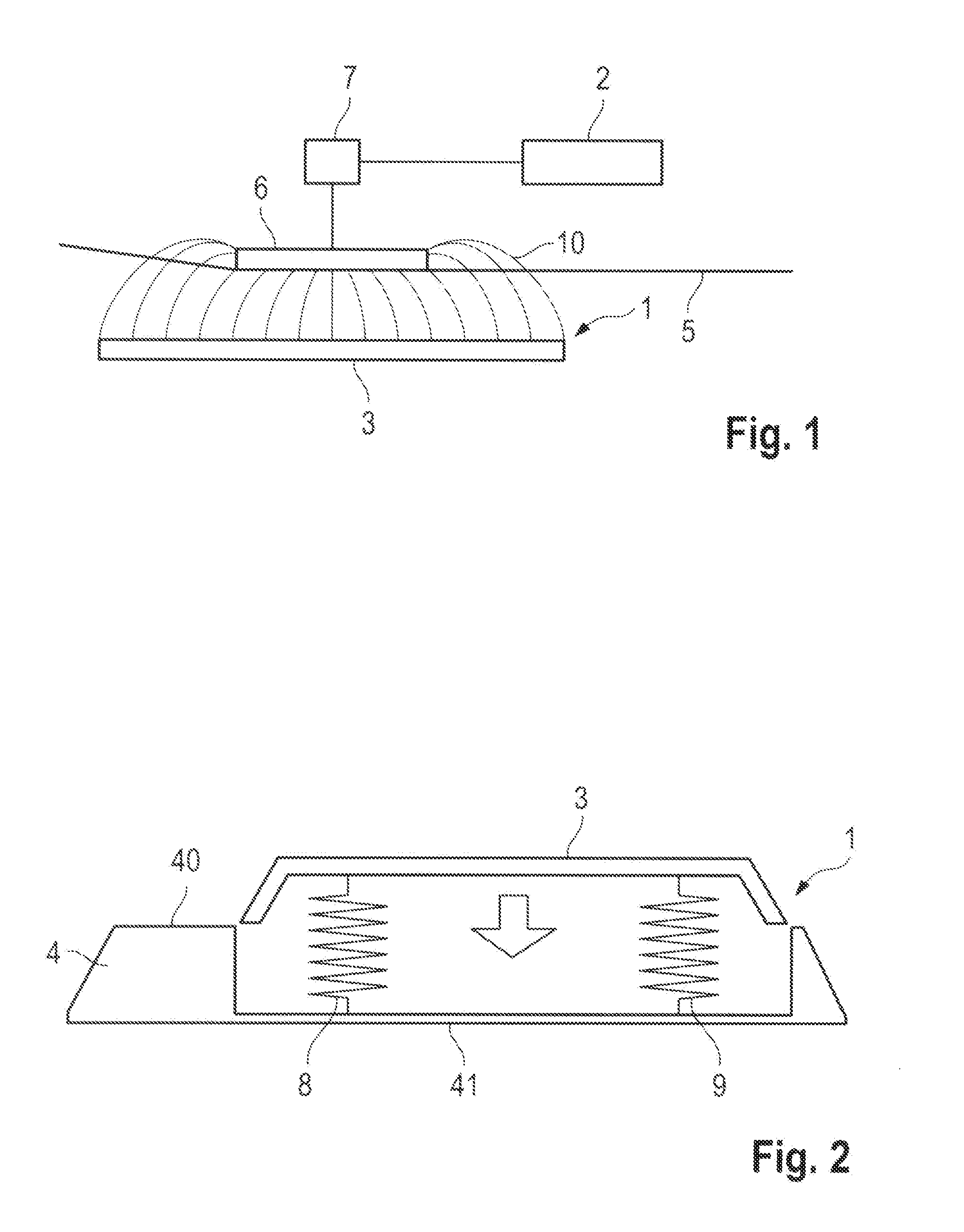
[0028]FIG. 1 schematically illustrates a device 1 that embodies the basic physical principle of contactless charging of an electrical energy storage means 2 of a motor vehicle that has as a drive an electrical machine or a combination of an electrical machine and an internal combustion engine (known as a hybrid electric vehicle). The device 1 has a primary coil 3 arranged in a bottom housing 4 that is represented in FIG. 2. The primary coil 3 closes off an upper housing opening of the bottom housing 4.

[0029]In the region of an underfloor 5, the motor vehicle has a secondary coil 6 that is connected to a rectifier means 7. The secondary coil 6 and the rectifier means 7 may be enclosed by a common housing. The rectifier means 7 is connected to the electrical energy storage means 2. For charging the electrical energy storage means 2 of the motor vehicle, the primary coil 3 and the secondary coil 6 must be aligned with one another in the x, y and z directions and positioned as exactly a...


PUM


Abstract

A device (1) for the contactless charging of an electrical energy storage (2) of a motor vehicle has at least one primary coil (3) arranged in a bottom housing (4) and connected to an electrical power supply. The device (1) is formed so that alternating current flowing in the primary coil (3) can generate an alternating magnetic field (10) to induce an alternating electrical voltage in a secondary coil (6) on the vehicle that is separated from the primary coil (3) by an air gap. Thus, a current flow that is variable over time and can be converted by a rectifier means on the vehicle into a direct current for charging the electrical energy storage connected to the rectifier means. The at least one primary coil (3) is connected to the bottom housing (4) in such a way to yield mechanically under the effect of an external compressive force.

Description

CROSS REFERENCE TO RELATED APPLICATION[0001]This application claims priority under 35 USC 119 to German Patent Appl. No. 10 2015 104 858.2 filed on Mar. 30, 2015, the entire disclosure of which is incorporated herein by reference.BACKGROUND[0002]1. Field of the Invention[0003]The invention relates to a device for the contactless charging of an electrical energy storage of a motor vehicle, comprising at least one primary coil that can be connected to an electrical power supply system, and a bottom housing, within which the primary coil is arranged. The device is formed so that the primary coil can be flowed through by an alternating current during operation and can generate an alternating magnetic field that can induce an alternating electrical voltage in a secondary coil on the vehicle that is separated from the primary coil by an air gap. As a result, a current flow that is variable over time and can be converted by a rectifier on the vehicle into a direct current for charging the ...

Claims


Application Information

Patent Timeline
Patent Type & Authority Applications(United States)
IPC IPC(8): B60L11/18
CPCB60L11/182B60L53/38Y02T10/7072Y02T90/14B60L53/12Y02T10/70Y02T90/12H02J7/00
Inventor KRISTOF, THOMASHERKE, DIRKUEFFING, MARINA
Owner DR ING H C F PORSCHE AG
Why Eureka
Try Eureka