
Device for holding and deploying apparatus for use in space

a technology for holding and deploying apparatus, which is applied in the direction of mechanical apparatus, cosmonautic components, cosmonautic parts, etc., can solve the problems of precarious reliability, complex solution, and complex construction point of view, and achieve the effect of small overall dimensions

Active Publication Date: 2016-10-06
AEREA
View PDF6 Cites 22 Cited by
  • Summary
  • Abstract
  • Description
  • Claims
  • Application Information

AI Technical Summary

Benefits of technology

The present invention provides a device for holding and deploying apparatus for use in space that is safe, reliable, and can be reused for several actuations. The device is easy to reset and has a small overall size, making it easy to install in limited space. The technical effects of the invention are that it overcomes the drawbacks of pyrotechnic systems and optimizes the use of shape memory alloy materials.

Problems solved by technology

These systems reveal one or more of the following drawbacks:actuation characterised by a high mechanical shock with potential impact on the functionality of the apparatus placed onboard on the satellite,release of pollutant material (solid, liquid or gaseous) and material that could potentially interfere with the onboard optical apparatus,checking the preload level is uneconomical and subjected to uncertainty elements,impossibility to operate manually,provision and use subjected to ITAR regulations (satellite exportation limitations),reset operations that can be carried out only at the premises of equipment supplier, with ensuing impact on costs, times and reliability,reset operations requiring the replacement of parts of the system, with impact on costs, times and reliability even in this case,limited number of implementations, if not just one.
This solution is not only very complex from a construction point of view but also poorly reliable from a functional point of view.
Though these solutions allow overcoming some of the problems mentioned beforehand, such as for example the disengagement of the moveable body without releasing material and with relatively low mechanical shocks, the reliability thereof is precarious, even due to the difficulty of efficiently controlling the actuation energy.
This system neither provides for nor allows the controlled separation between the two elements connected by the shape memory alloy torsional bar.

Method used


Image

  • Device for holding and deploying apparatus for use in space
  • Device for holding and deploying apparatus for use in space
  • Device for holding and deploying apparatus for use in space

Examples


Embodiment Construction

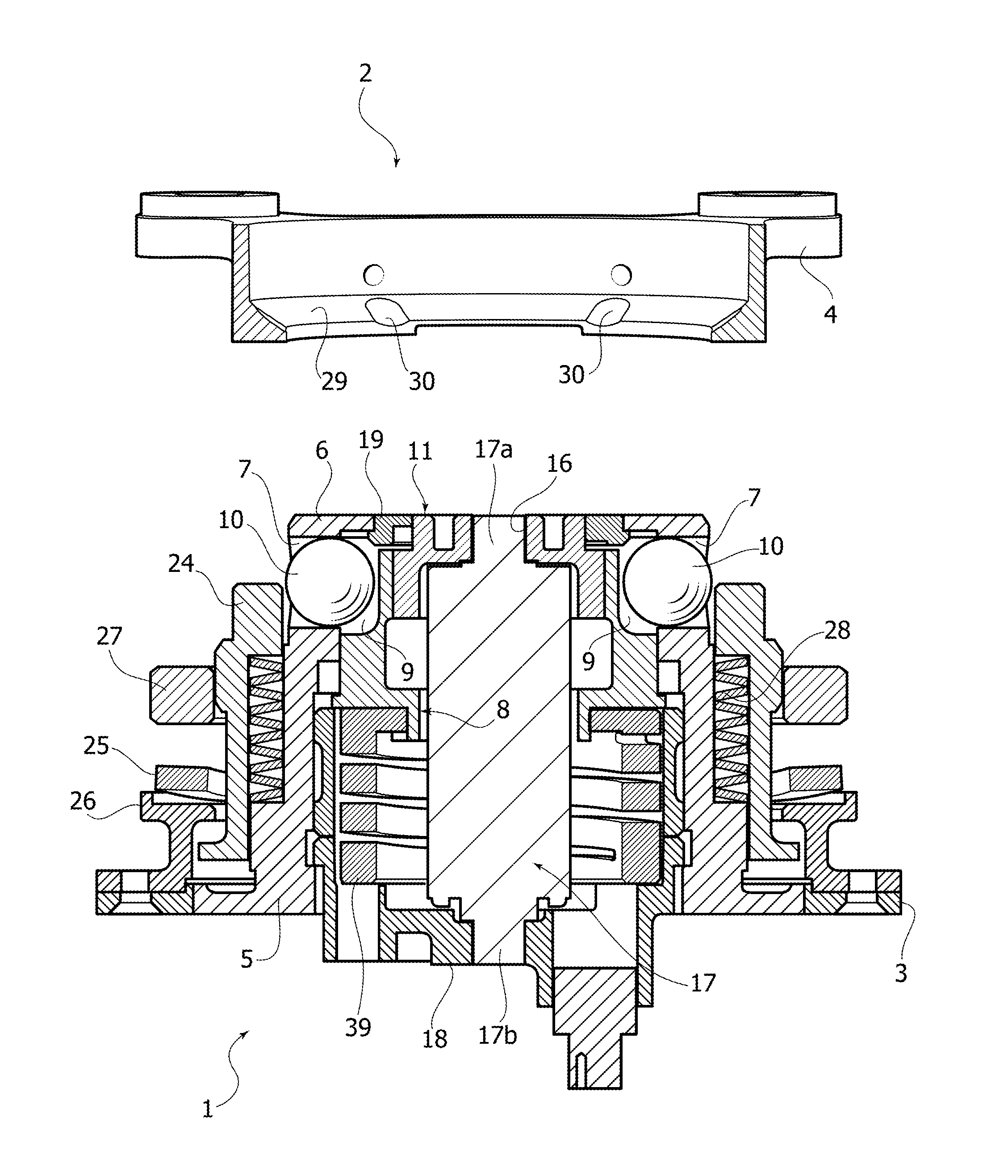
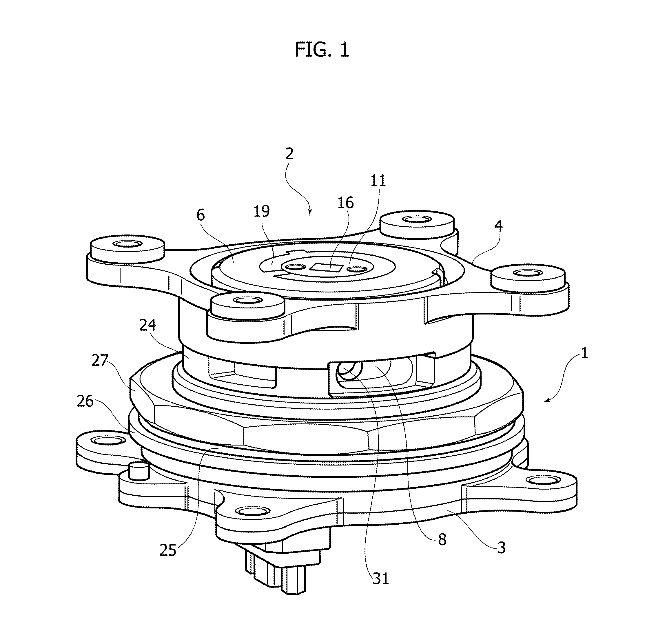
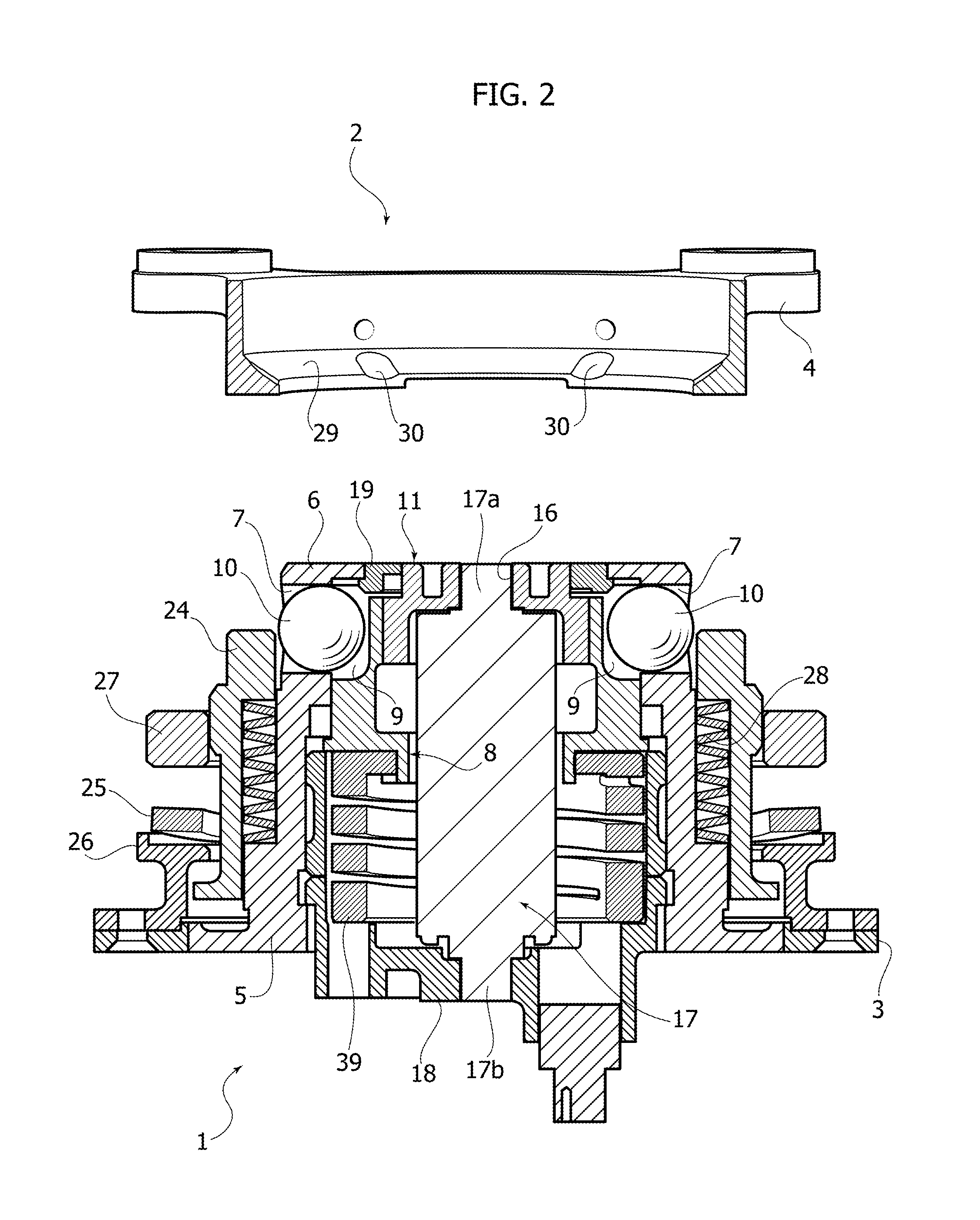
[0049]The embodiment of the device for the holding and deploying the apparatus for use in space represented in the drawings essentially comprises a fixed body 1 and a moveable body 2 coaxially connected to each other in a separable fashion and provided with respective flanges 3, 4 for example for fixing to a satellite and a solar panel. The fixed and moveable bodies 1, 2 are held integrally joined to each other in the steps of launching and putting in orbit, as represented in FIG. 1, and thus disengaged to allow deployment of the solar panel.

[0050]The fixed body 1 comprises a substantially cylindrical retention cable element 5 whose end portion 6, opposite to the flange 3, is formed on the lateral wall thereof with a crown of equally-spaced angularly radial holes 7.

[0051]In such end part 6 of the retention element 5 there is coaxially inserted a hollow spool 8 formed with a crown of recesses 9 equally-spaced angularly like the radial holes 7. A crown of balls 10 cooperates with the ...


PUM


Abstract

A device for holding and deploying apparatus for use in space includes a fixed body and a movable body coaxially connected to each other through balls displaceable from a retention position to a release position, and a shape memory alloy actuator remote-controllable to displace the balls from the retention position to the release position and the ensuing separation of the moveable body from the fixed body under the action of axial thrust elastic means. The shape memory alloy actuator consists of a torsionally-deformable bar.

Description

CROSS-REFERENCE TO RELATED APPLICATIONS[0001]This application claims priority to Italian Patent application No. 102015000010459 filed on Mar. 31, 2015, the entire disclosure of which is incorporated herein by reference.FIELD OF THE INVENTION[0002]The present invention refers to devices for holding and deploying apparatus for use in the space, such as for example solar panels and the like. Devices thus made typically include a fixed body constrained to a satellite intended to put in the orbit, and a mobile body constrained to the apparatus. The mobile body can be deployed or separated from the fixed body through a remote controllable actuator.[0003]STATE OF THE PRIOR ART[0004]Currently known hold and deploy devices of this type generally utilise, for deploying or separating the moveable body from the fixed body, pyrotechnic systems based on the detonation of small explosive charges. These systems reveal one or more of the following drawbacks:[0005]actuation characterised by a high me...

Claims


Application Information

Patent Timeline
Patent Type & Authority Applications(United States)
IPC IPC(8): F03G7/06B64G1/22
CPCF03G7/065B64G1/44B64G1/222B64G1/2228
Inventor CASSANELLI, RUGGERO
Owner AEREA
Learn More