Method and device for frequency adjustment of a magnetic resonance imaging apparatus using an inversion pulse

a magnetic resonance imaging and frequency adjustment technology, applied in the direction of magnetic measurement, instruments, measurements using nmr, etc., can solve the problems of difficult automatic detection of silicone, inability to accurately determine the system frequency based on the previously scanned frequency spectrum, and further hinder the correct allocation of maxima in this conventional method, so as to achieve less time-consuming and reliable

Inactive Publication Date: 2016-10-06
SIEMENS AG
View PDF3 Cites 5 Cited by
  • Summary
  • Abstract
  • Description
  • Claims
  • Application Information

AI Technical Summary

Benefits of technology

[0015]An object of the present invention is to provide a more effective and more reliable method

Problems solved by technology

A clear and precise determination of the system frequency based on the previously scanned frequency spectrum is therefore often associated with difficulties.
In addition, it is often not known which materials are contained in a region under examination, so that a correct allocation of the maxima is further hindered.
However, this requires additional operational steps which also require a certain degree of experience from the operating personnel.
However, an automatic detection of silicone is not possible in this conventional method.
If the external c

Method used


Image

  • Method and device for frequency adjustment of a magnetic resonance imaging apparatus using an inversion pulse
  • Method and device for frequency adjustment of a magnetic resonance imaging apparatus using an inversion pulse
  • Method and device for frequency adjustment of a magnetic resonance imaging apparatus using an inversion pulse

Examples


Embodiment Construction

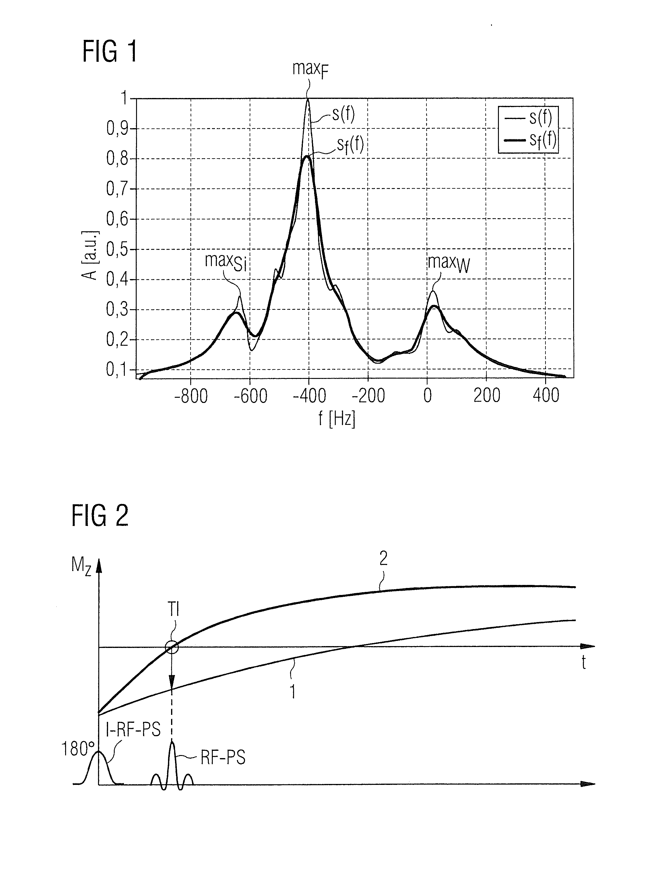
[0045]FIG. 1 shows a frequency spectrum s(f) with three maxima. The amplitude A of the frequency spectrum s(f) is plotted in arbitrary units a.u. against the frequency f or the deviation of the frequency from the system frequency fw. In order to acquire the frequency spectrum, in a magnetic resonance system (see FIG. 6), a so-called STEAM sequence is generated and herein stimulated magnetic resonance signals, also called echo signals, are read out. The frequency spectrum s(f) is typically obtained by summing individual spectral curves which are each determined on the basis of signals from individual channels of the antenna system of the magnetic resonance system. Typically, on the basis of the acquired overall frequency spectrum s(f), a filtered frequency spectrum sf(f) is generated wherein a typical filter width of the filter with which the filtered frequency spectrum sf(f) was generated is, for example, 1 ppm. The filtered frequency spectrum sf(f) is taken as the basis for the fur...


PUM


Abstract

In a magnetic resonance (MR) system and method for determining an MR system frequency for a region to be examined that has multiple materials therein, a first frequency spectrum is acquired by the execution of a first RF excitation sequence. A second frequency spectrum for the region is acquired by radiation of an RF inversion pulse and execution of a second RF excitation sequence, at the point in time at which the relaxation curve of one of the materials has a zero-crossing. Subsequently, echo signals excited by the second RF excitation sequence are read out, from which a frequency spectrum is determined. The first frequency spectrum and the second frequency spectrum are compared. On the basis of the comparison, maxima of the first frequency spectrum are allocated to different materials. The system frequency is determined on the basis of the allocation of the maxima.

Description

BACKGROUND OF THE INVENTION[0001]1. Field of the Invention[0002]The invention concerns a method for determining a system frequency for a magnetic resonance (MR) apparatus. The invention further concerns a system frequency determining device, as well as a magnetic resonance system embodying such a device.[0003]2. Description of the Prior Art[0004]In the generation of magnetic resonance scans, the body to be examined is subjected to a relatively large basic magnetic field of, for example, 1.5 Tesla, 3 Tesla or in relatively new high magnetic field systems, even of 7 Tesla. Then, using a suitable antenna system, a radio-frequency excitation signal is emitted which serves to tilt the nuclear spin of particular atoms, stimulated into resonance by this radio-frequency field, through a particular flip angle relative to the magnetic field lines of the basic magnetic field. The radio-frequency signal radiated by the nuclear spins during the relaxation thereof, the magnetic resonance signal, ...

Claims


Application Information

Patent Timeline
IPC IPC(8): G01R33/48G01R33/561G01R33/483
CPCG01R33/4828G01R33/5617G01R33/483G01R33/5602G01R33/583
Inventor NIEDERLOEHNER, DANIELSCHNUR, GUENTER
Owner SIEMENS AG
Why Eureka
Try Eureka