Rotor, Method of Manufacturing the Same, and Motor Including the Rotor

a technology of rotor and rotor body, which is applied in the direction of magnetic circuit rotating parts, dynamo-electric machines, and magnetic circuit shape/form/construction, etc. it can solve the problems of difficult adhesive application and inability to fix the magnet, so as to reduce process costs, prevent noise and vibration, and eliminate unstable operation

Active Publication Date: 2016-10-06
LG INNOTEK CO LTD
View PDF7 Cites 3 Cited by
  • Summary
  • Abstract
  • Description
  • Claims
  • Application Information

AI Technical Summary

Benefits of technology

[0008]The present invention is directed to a motor which is reliable by fixedly inserting magnets inserted into a rotor with no adhesive and implementing a magnet fixing pattern at a peripheral portion of a magnet insertion hole in an upper surface of a rotor member so as to eliminate an unstable operation and foreign material generation due to adhesive delamination caused by an external environmental change, and particularly, may prevent noises and vibrations due to a fixing defect of the magnet from being generated and also reduce process costs by implementing a stable fixing structure of the magnet using a fixing method by an axial pressure of the rotor.

Problems solved by technology

However, a method of fixing using only an adhesive causes problems in which the magnet moves from an initial mounting position, a foreign material due to delamination of the adhesive is generated, and the magnet cannot be fixed due to glass transition at a high temperature since adhesion of the adhesive fixing the magnet is degraded when the motor is used for a long period or is used for long hours at a high temperature.
To solve the above problems, an adhesive capable of enduring a high temperature is required, but an application of the adhesive is difficult due to some problems of costs, ensuring permanent stability during high speed rotation, and economic feasibility.

Method used


Image

  • Rotor, Method of Manufacturing the Same, and Motor Including the Rotor
  • Rotor, Method of Manufacturing the Same, and Motor Including the Rotor
  • Rotor, Method of Manufacturing the Same, and Motor Including the Rotor

Examples


Embodiment Construction

[0016]Hereinafter, configurations and operations according to the present invention will be described in detail with reference to the accompanying drawings. In the description with reference to the accompanying drawings, like elements are designated by like reference numerals regardless of drawing numbers, and duplicated descriptions thereof will be omitted. Although the terms “first,”“second,” etc. may be used herein to describe various elements, these elements are not be limited by these terms. These terms are only used to distinguish one element from another.

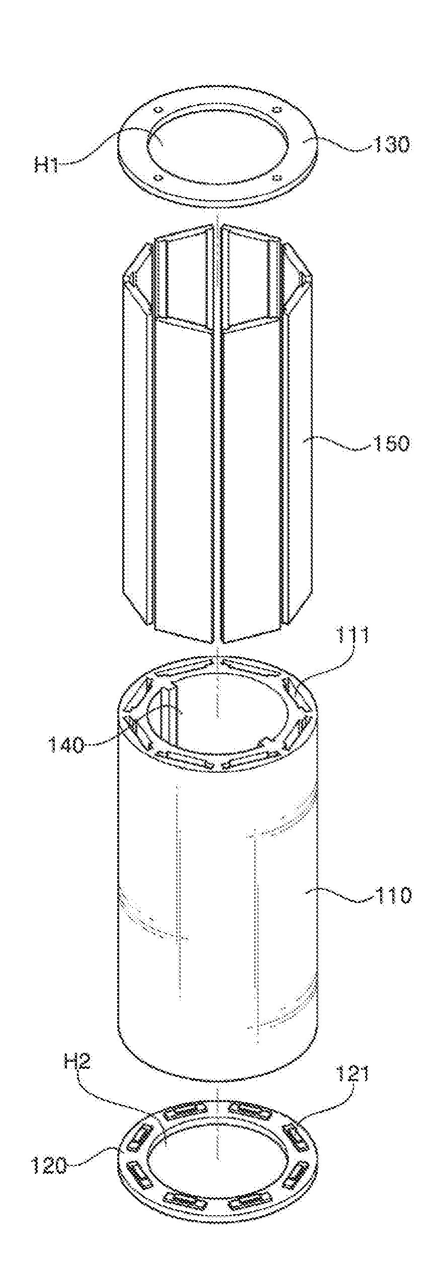
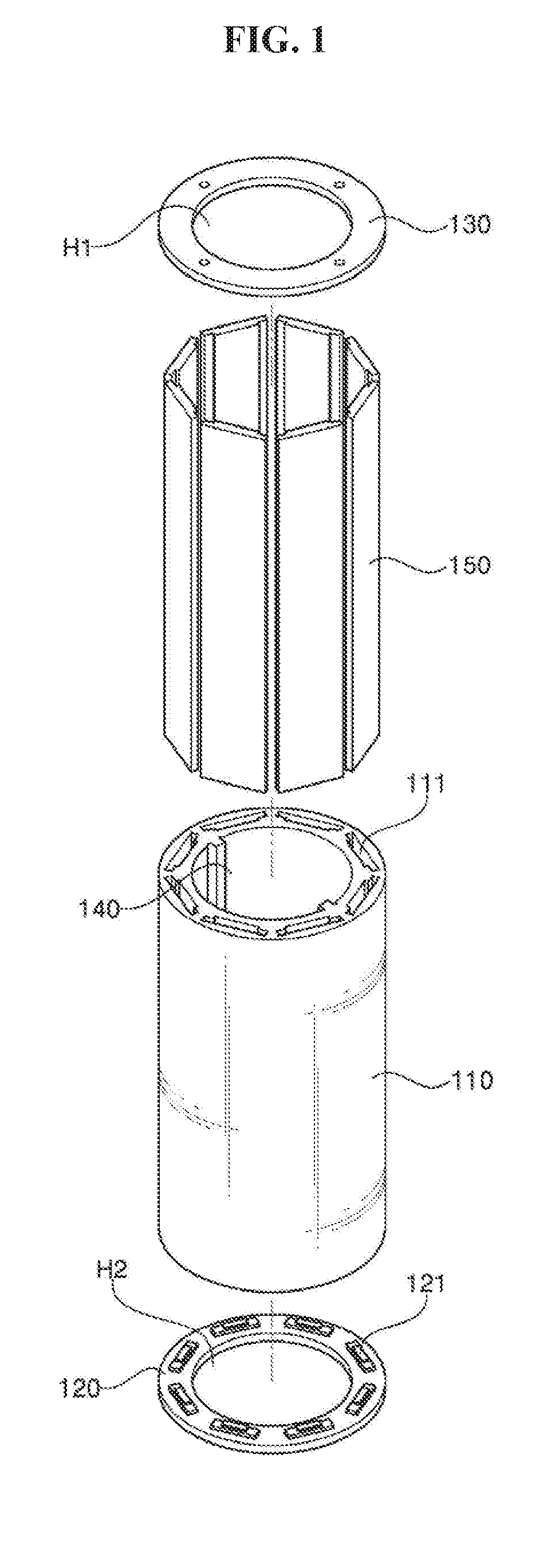
[0017]FIG. 1 is a schematic view for describing a structure of a rotor according to an embodiment of the present invention and FIG. 2 is a schematic view showing an enlarged main portion of the rotor in FIG. 1. In addition, FIG. 3 is a cross-sectional schematic view for describing a structure of the rotor according to the embodiment of the present invention and FIG. 4 is a process schematic view for describing a process of ma...


PUM


Abstract

The present invention relates to a motor for a vehicle and a rotor applied thereto. Provided is a rotor including a rotor core in which a plurality of rotor core members are stacked and a plurality of magnets inserted into magnet insertion holes of the rotor core, and further including fixing patterns that protrude toward the center of the magnet insertion holes from one sides of the magnet insertion holes of the rotor core members respectively disposed at an uppermost layer and a lowermost layer.

Description

CROSS-REFERENCE TO RELATED APPLICATION[0001]This application claims priority under 35 USC. §119 to Korean Patent Application No. 2015-0045535, filed Mar. 31, 2015, which is hereby incorporated by reference in their entirety.BACKGROUND[0002]1. Field of the Invention[0003]The present invention relates to a motor for a vehicle and a rotor applied to the motor.[0004]2. Discussion of Related Art[0005]As a motor for a vehicle has been developed to a high specification such as high torque and high speed, a robust design is necessarily required for a rotor assembly structure applied to the motor. Generally, the rotor structure applied to an interior permanent magnet (IPM) motor has a structure in which a magnet is inserted into a stacked rotor core formed by stacking a plurality of rotor core members with a disk-shape.[0006]In this case, the magnet inserted into the rotor core fixedly adheres to a magnet insertion hole using an adhesive, etc. However, a method of fixing using only an adhesi...

Claims


Application Information

Patent Timeline
Patent Type & Authority Applications(United States)
IPC IPC(8): H02K1/27H02K21/14H02K15/03
CPCH02K1/276H02K21/14H02K15/03H02K1/278H02K2213/03H02K1/28
Inventor OH, JI HWAN
Owner LG INNOTEK CO LTD
Why Eureka
Try Eureka