Spinal implants configured for tissue sparing angle of insertion and related methods

a tissue sparing angle and implant technology, applied in the field of minimally invasive spinal implants and spinal fusion implants, can solve the problems of rigidly fixed attachment means that can loosen, dislodge or potentially damage one or more vertebral bodies, and may become weakened, damaged or broken, etc., to facilitate fusion, promote sagittal balance, and maximize endplate coverage

Active Publication Date: 2016-10-13
CENTINEL SPINE LLC
View PDF3 Cites 7 Cited by
  • Summary
  • Abstract
  • Description
  • Claims
  • Application Information

AI Technical Summary

Benefits of technology

[0008]The embodiments provide spinal implants that are configured for a tissue sparing or an oblique angular approach to a patient's intervertebral disc space. The spinal implants may facilitate fusion, and include anti-migration and anti-rotation features as well as visualization features to assist in the implantation and verify proper placement. The implants support a narrow access oblique surgical approach while maximizing endplate coverage and promoting sagittal balance. The oblique approach provides better access to more spinal levels and is potentially less invasive than other approaches including midline and lateral approaches.

Problems solved by technology

These parts may become weakened, damaged or broken as a result of trauma, injury, or disease (e.g., by tumor, autoimmune disease), or as a result of wear over time, or degeneration caused by the normal aging process.
Unfortunately, after implantation the implants tend to subside, or settle, into the surrounding environment as the patient's weight is exerted upon the implant.
In some cases, this subsidence may cause the rigidly fixed attachment means to either loosen, dislodge or potentially damage one or more of the vertebral bodies.

Method used


Image

  • Spinal implants configured for tissue sparing angle of insertion and related methods
  • Spinal implants configured for tissue sparing angle of insertion and related methods
  • Spinal implants configured for tissue sparing angle of insertion and related methods

Examples


Embodiment Construction

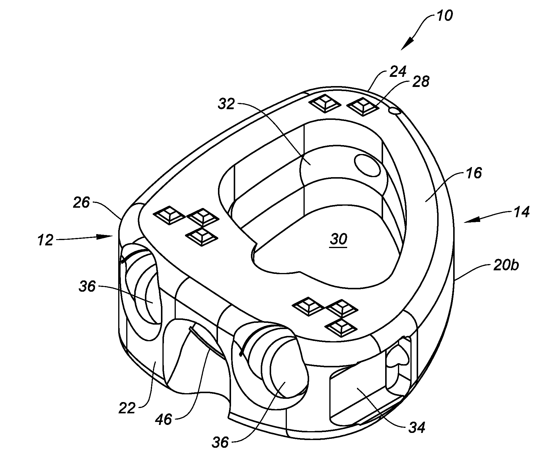
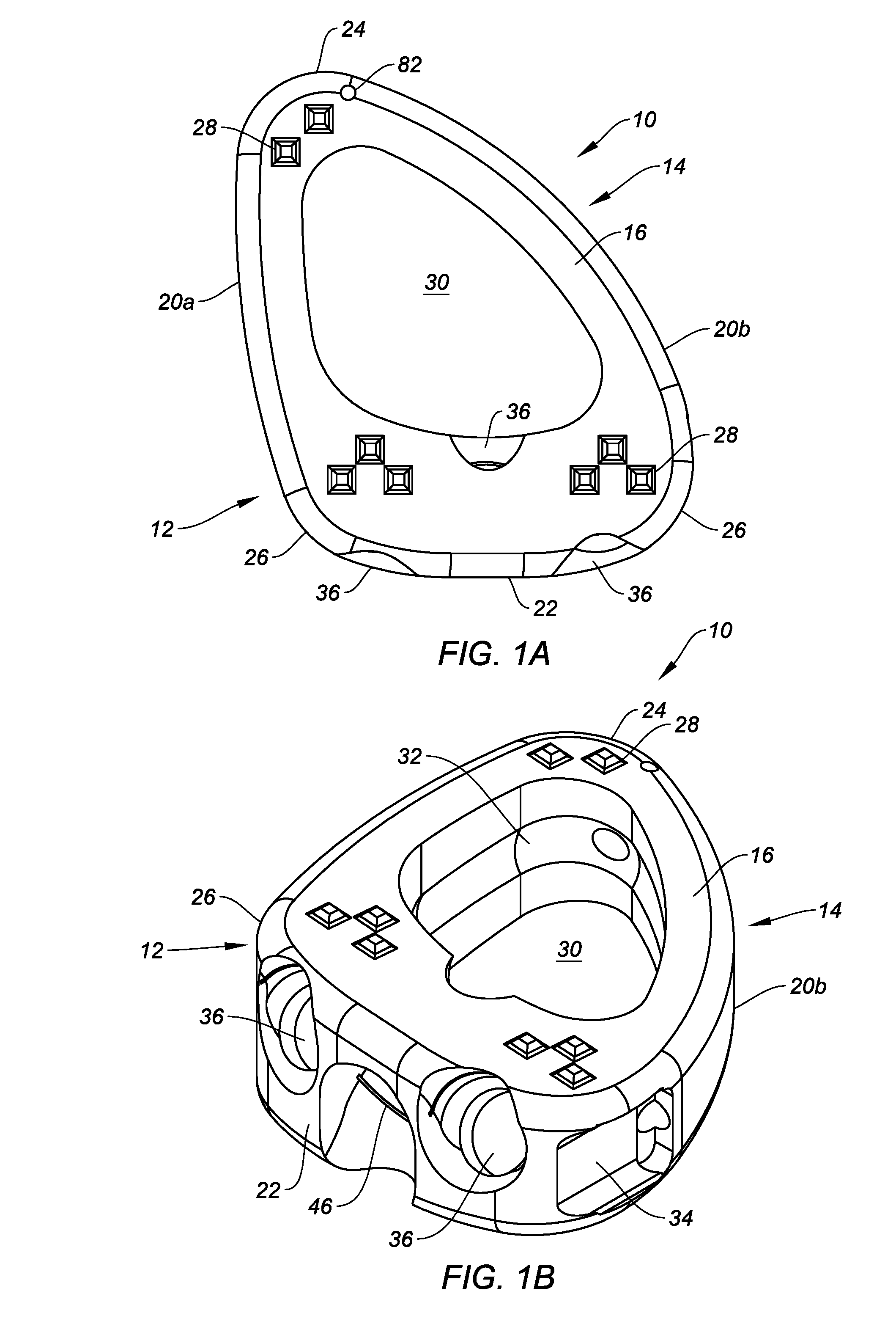
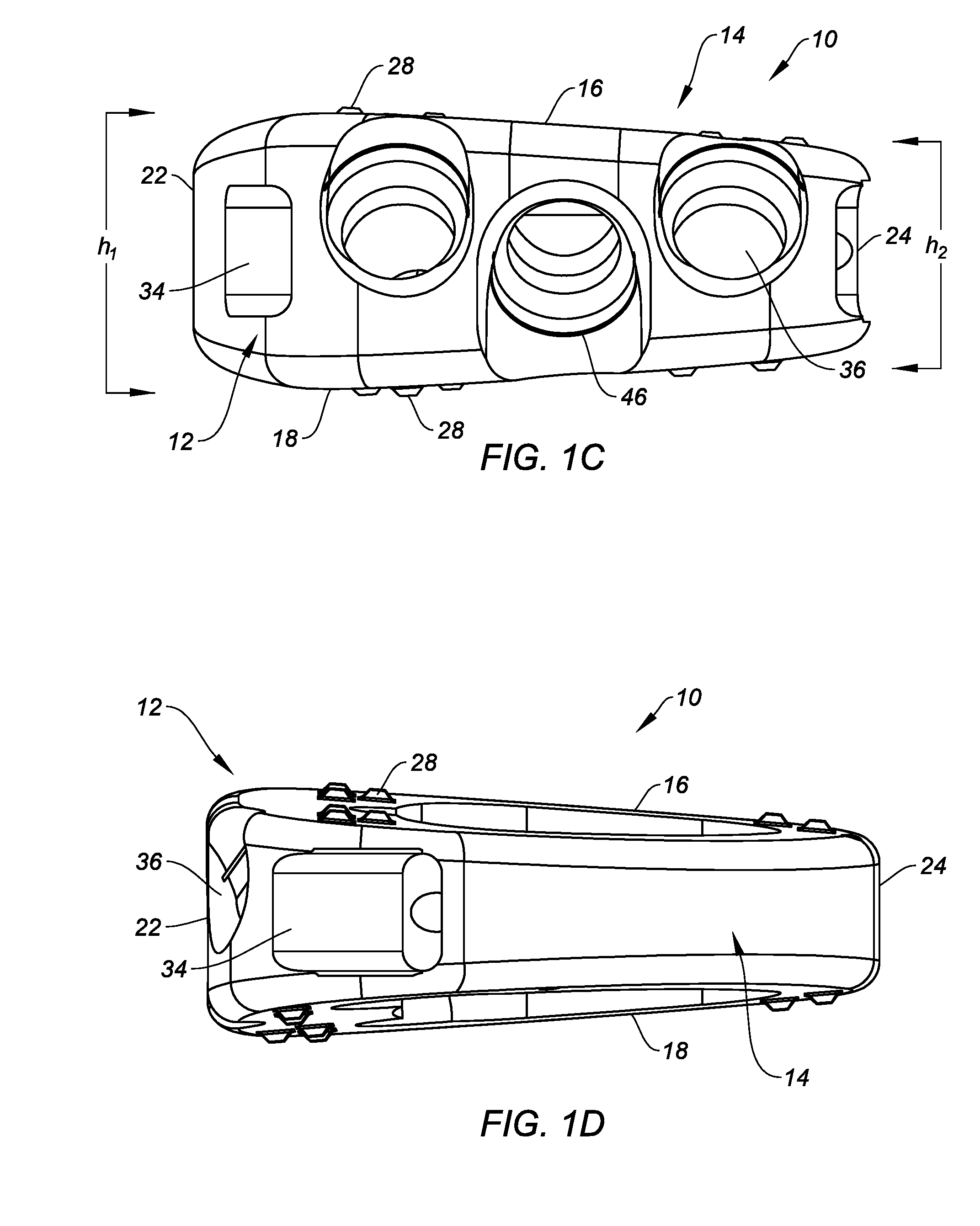
[0031]The present disclosure provides various spinal implants that are configured for an oblique angular approach into a patient's intervertebral disc space. The spinal implant may be introduced through a narrow access window, while maximizing endplate coverage and promoting sagittal balance. The oblique approach may provide better access to more spinal levels, and may be potentially less invasive compared to midline or lateral approaches.

[0032]In accordance with one exemplary embodiment, a spinal implant is provided having an upper surface, a lower surface, a wall at the anterior portion of the implant, two sidewalls connecting the upper and lower surfaces and converging at a nose or tip near the anterior portion of the implant, and one or more apertures within the posterior portion for receiving at least one fixation element, wherein the implant is configured for insertion at an oblique angle into the patient's lumbar spine. The spinal implant may additionally include anti-migrati...


PUM

PropertyMeasurementUnit
diameteraaaaaaaaaa
heightsaaaaaaaaaa
heightsaaaaaaaaaa

Abstract

Spinal implants that are configured for a minimally invasive approach to a patient's intervertebral disc space, optimized to avoid blood vessels and nervous tissue, maximizing endplate coverage and promoting sagittal balance, are provided. Insertion and fixation can be accomplished through a narrow access window, thereby allowing better access to more spinal levels while being less invasive than other approaches. The spinal implants may facilitate fusion, and include visualization features to assist in the implantation and verify proper placement and vary segmental angle of lordosis. Methods of implanting the spinal implants to treat a patient's spine are also disclosed.

Description

CROSS-REFERENCE TO RELATED APPLICATIONS[0001]This application claims benefit of U.S. Provisional Application No. 62 / 145,161, filed on Apr. 9, 2015, and entitled “SPINAL IMPLANT CONFIGURED FOR OBLIQUE ANGLE INSERTION AND RELATED METHODS,” the entire contents of which are incorporated herein by reference.TECHNICAL FIELD[0002]The present disclosure relates to orthopedic implants, and more particularly, to minimally invasive spinal implants that facilitate fusion of bone segments and associated methods. Even more particularly, the disclosure relates to spinal fusion implants configured for insertion along an oblique angular trajectory into the lumbar spine, and related methods.BACKGROUND[0003]The integrity of the spine and its subcomponents like the vertebral bodies and intervertebral discs, both of which are well known structural body parts that make up the spine, is a key factor to maintaining a patient's good health. These parts may become weakened, damaged or broken as a result of t...

Claims


Application Information

Patent Timeline
Patent Type & Authority Applications(United States)
IPC IPC(8): A61F2/44A61F2/30
CPCA61F2/4455A61F2/30771A61F2002/3082A61F2002/3008A61F2002/30784A61F2002/30266A61F2002/30841A61F2002/30822A61F2002/30187A61F2002/30879A61F2310/00407A61F2002/30843A61F2/4611A61F2002/30787A61F2002/30062A61F2002/4627A61F2002/30828A61F2002/30593
Inventor BOST, STEPHANIE M.MCQUAIDE, ANDREW J.PARRY, JOHN J.
Owner CENTINEL SPINE LLC
Why Eureka
Try Eureka