
Vehicle lamp

Active Publication Date: 2016-10-13
KOITO MFG CO LTD
View PDF21 Cites 9 Cited by
  • Summary
  • Abstract
  • Description
  • Claims
  • Application Information

AI Technical Summary

Benefits of technology

The vehicle lamp described in this patent allows for the control of the light source through two modes: a first mode that quickly turns off the light source in response to certain situations (such as approaching a preceding vehicle or detecting a drop in brightness) to enhance safety, and a second mode that gradually reduces the quantity of light to improve safety and comfort for the driver. The light source can be controlled without additional circuitry and control, and the light distribution pattern can be adjusted to provide a more comfortable illumination for the driver during driving on a curve. Overall, this vehicle lamp provides precise control of the light source for improved safety and comfort for the driver.

Problems solved by technology

A light source with high luminance causes a problem of dazzling a preceding vehicle and / or a pedestrian while it provides high visibility.

Method used


Image

  • Vehicle lamp
  • Vehicle lamp
  • Vehicle lamp

Examples


first modified example

[0072]The mode switching control is not limited to the one described in the embodiment.

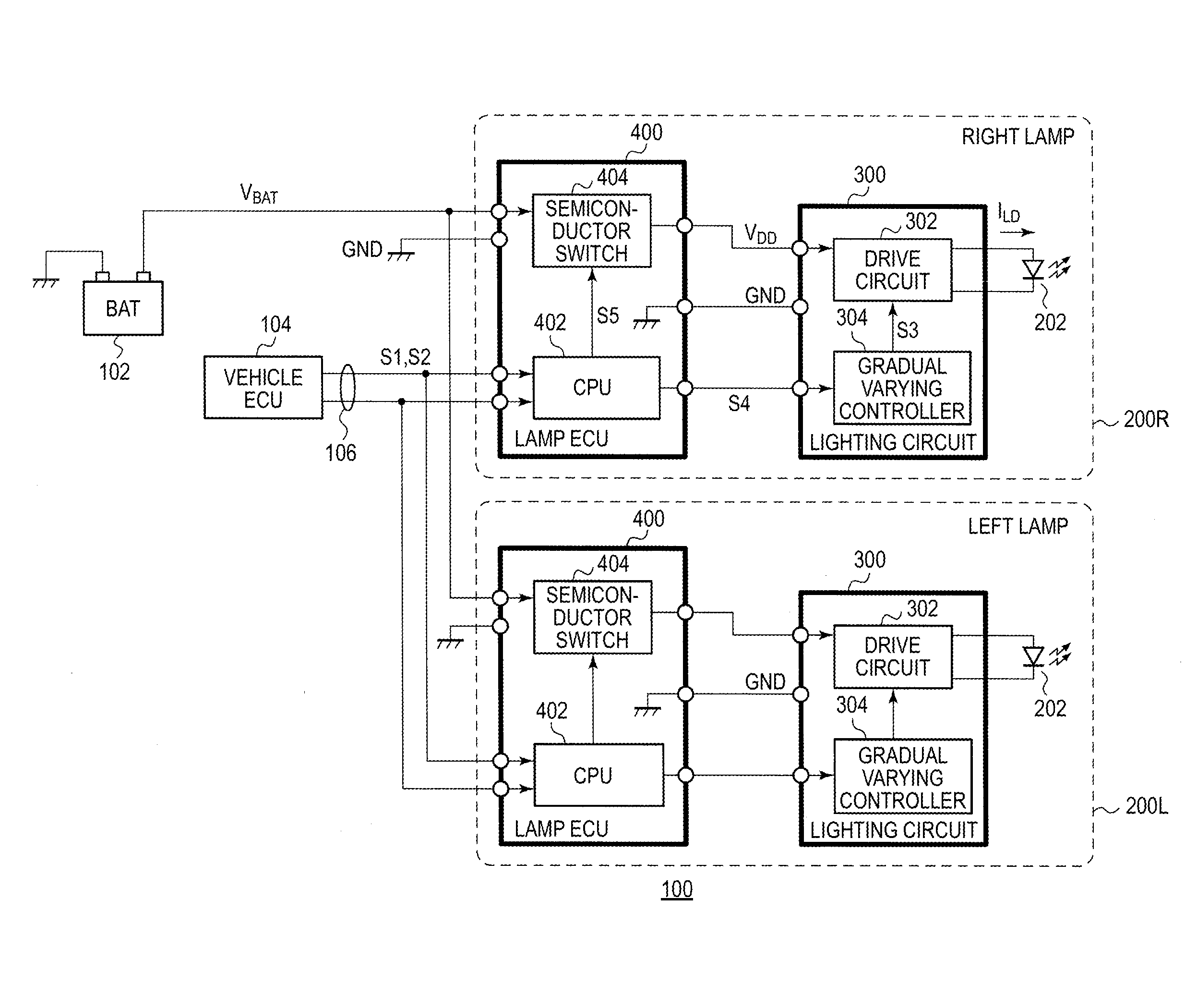
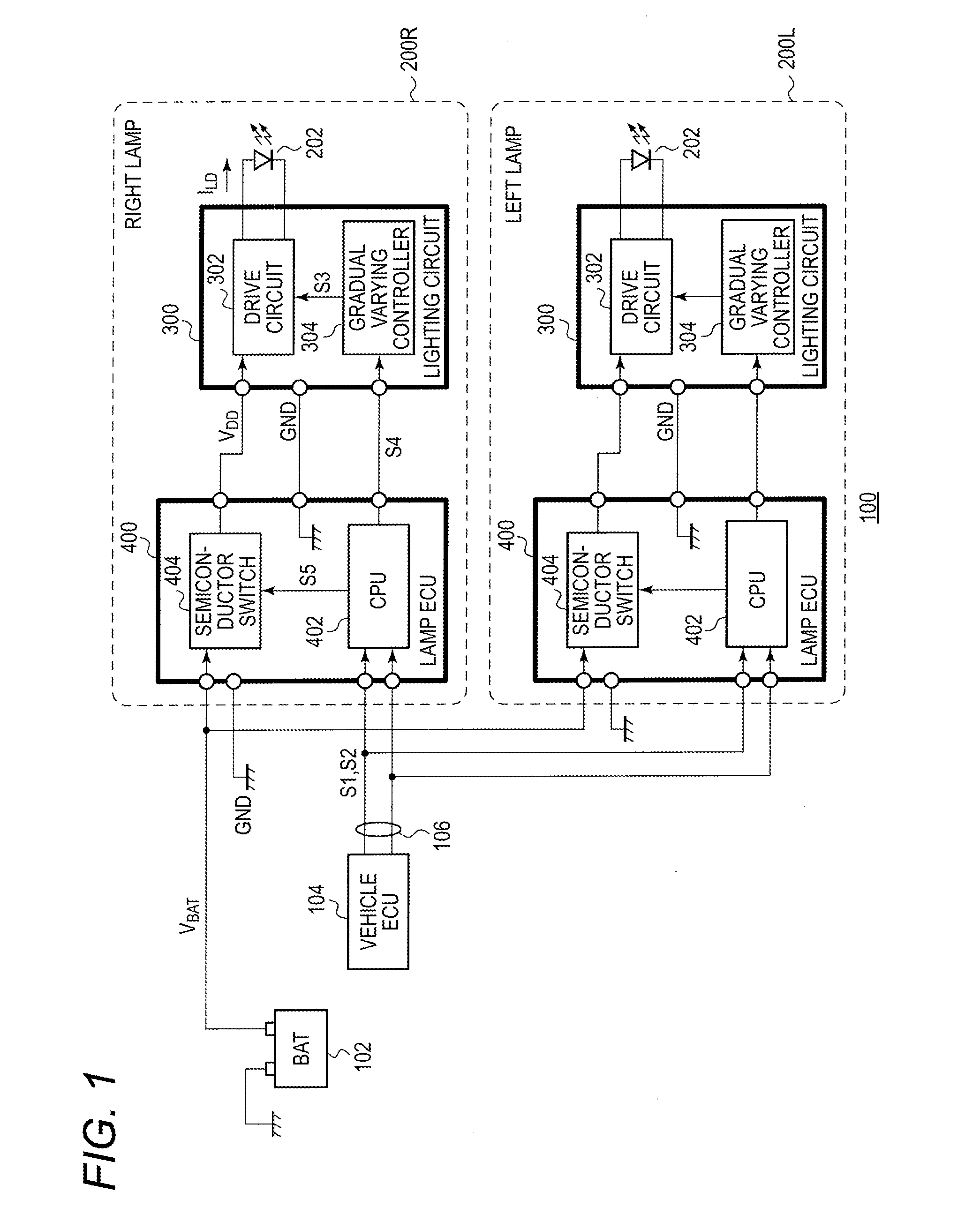
[0073]In a first modified example, the gradual varying controller 304 is configured so as to generate two dimming signals S3a, S3b that correspond to the first mode and the second mode, respectively. The dimming signal S3a that corresponds to the first mode should be the signal shifted immediately to the turn on or off when ordering signal S4 is shifted to the turn off level. Then, the CPU 402 gives an instruction to turn on or off the light source 202 via the turn on or off ordering signal S4 and informs the gradual varying controller 304 of the mode selected via a signal separate from the turn on or off ordering signal S4. With this modified example, the light source 202 can be switched between the plurality of modes.

second modified example

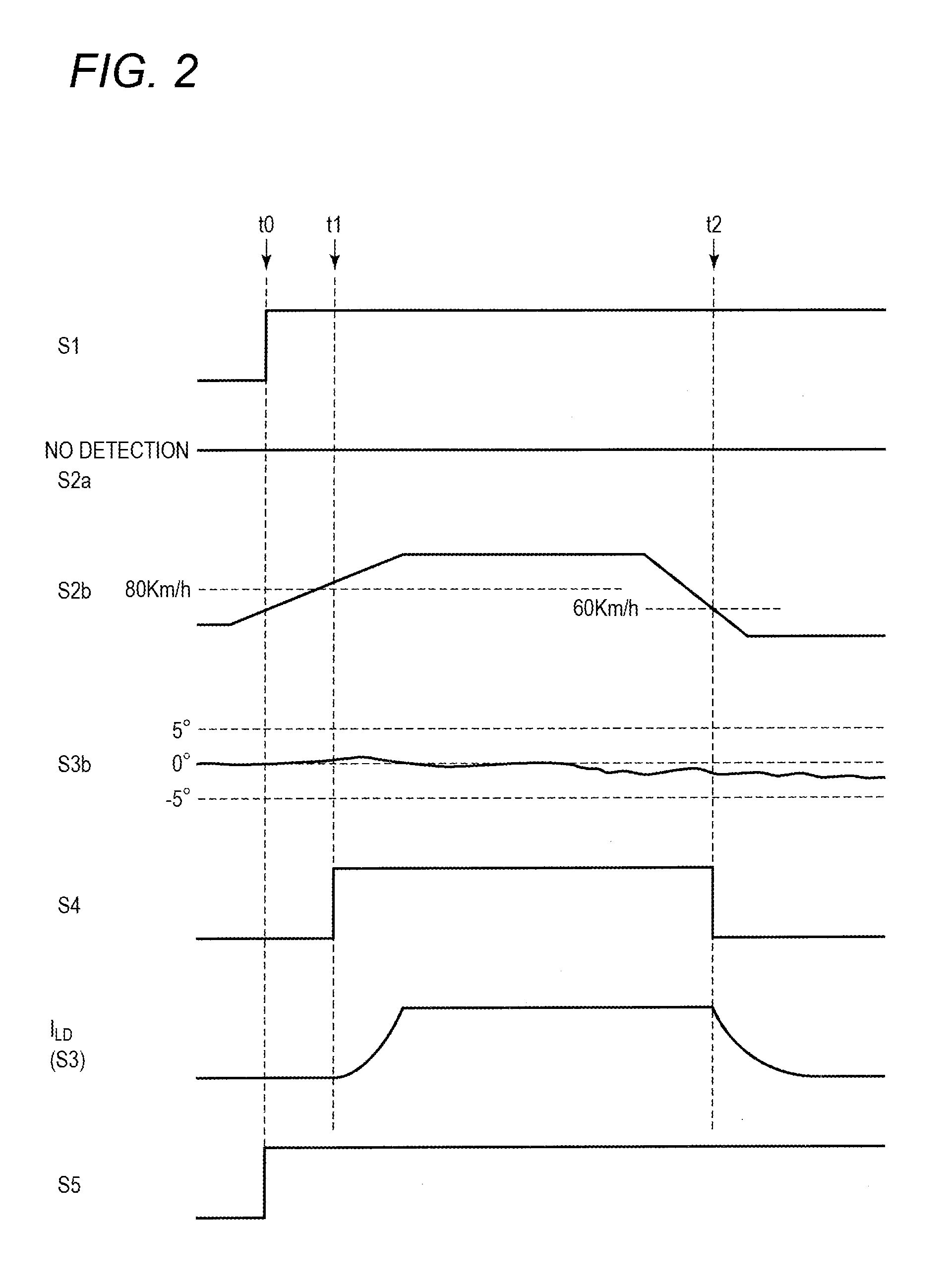
[0074]In the embodiment, the light source 202 is switched between the first mode and the second mode. However, the light source 202 may be switched among modes more than two. In other words, the processor may vary the gradual varying time in the second mode according to a cause for turning off the light source. For example, when a preceding vehicle is detected, the first mode is selected. Then, when the light source 202 is turned off based on a reduction in vehicle speed, a second mode with a short gradual varying time is selected, and when the light source 202 is turned off based on the steering angle, a second mode with a long gradual varying time is selected. By adopting this configuration, the mode switching control can be carried out more appropriately according to the situation of the vehicle.

third modified example

[0075]In the embodiment, the driving information S2 that is inputted into the CPU 402 is described as including the vehicle speed, the presence or absence of a preceding vehicle and the steering angle. However, in addition to them, the presence or absence of a pedestrian, information from a car navigation system, information (pitch, roll, yaw) from an acceleration sensor or a gyro-sensor, and whether a door is opened or closed may be considered as the driving information S2. Then, any one or any combination of these pieces of information can be used as the driving information S2. The cause for turning off the light source 202 in the first mode is not limited to the detection of a preceding vehicle.


PUM


Abstract

A vehicle lamp comprises a light source, a drive circuit, a CPU, and a gradual varying controller. The drive circuit supplies a driving current to a light source according to a dimming signal. The CPU generates a turn on or off ordering signal that instructs the light source to be turned on or off according to an instruction from a vehicle and information that indicates a driving situation. The gradual varying controller generates the dimming signal that varies gradually with time in response to the turn on or off ordering signal. The vehicle lamp can be switched between a first mode in which the light source is turned off momentarily and a second mode in which the light source is turned off gradually.

Description

CROSS-REFERENCE TO RELATED APPLICATION[0001]The present application claims the benefit of priority of Japanese Patent Application No. 2015-078686, filed on Apr. 7, 2015, which is incorporated herein by reference.TECHNICAL FIELD[0002]The present invention relates to a vehicle lamp for use on a motor vehicle.BACKGROUND ART[0003]The main stream of conventional vehicle lamps has been halogen lamps and HIDs (High Intensity Discharge) lamps. In recent years, however, vehicle lamps have been developed in which a semiconductor light source such as an LED (Light Emitting Diode) or a laser diode (also referred to as a semiconductor laser) is used as a light source.[0004]A vehicle lamp has been developed which includes an additional high beam configured to illuminate an area lying farther than an area to be illuminated by a normal high beam with a view to enhancing the visibility of such a farther area. A laser diode is used as a light source for the additional high beam because high direction...

Claims


Application Information

Patent Timeline
IPC IPC(8): B60Q1/14H05B44/00
CPCB60Q1/1407B60Q2300/322B60Q2300/41B60Q1/143H05B45/10H05B45/50H05B45/00H05B45/37H05B45/48H05B45/345H05B45/325H05B45/375H05B47/20
Inventor ICHIKAWA, TOMOYUKI
Owner KOITO MFG CO LTD
Features
  • Generate Ideas
  • Intellectual Property
  • Life Sciences
  • Materials
  • Tech Scout
  • Unparalleled Data Quality
  • Higher Quality Content
  • 60% Fewer Hallucinations
Learn More