Hybrid vapor compression membrane distillation drive assemblyand method of use

Inactive Publication Date: 2016-10-13
GENERAL ELECTRIC CO
View PDF2 Cites 0 Cited by
  • Summary
  • Abstract
  • Description
  • Claims
  • Application Information

AI Technical Summary

Benefits of technology

[0010]In an alternate embodiment, a membrane distillation system is provided in accordance with another embodiment. The membrane distillation system comprises a membrane distillation module and a hybrid vapor compression drive assembly in fluidic communication with the membrane distillation module. The hybrid vapor compression drive assembly is configured to introduce an intermediate pressure steam to a high temperature side of the membrane distillation module and extract a low pressure steam, having a pressure less than the intermediate pressure steam, from a low temperature side of the membrane distillation module, thereby creating a temperature gradient across of the

Problems solved by technology

In this scenario, steam availability for any additional use, such as by the membrane distillation system, may suffer wide variations throughout the day, as a result of the instantaneous steam demand of known system equipment.
When steam demand f

Method used


Image

  • Hybrid vapor compression membrane distillation drive assemblyand method of use
  • Hybrid vapor compression membrane distillation drive assemblyand method of use
  • Hybrid vapor compression membrane distillation drive assemblyand method of use

Examples


Example

[0018]Preferred embodiments of the present disclosure will be described here in below with reference to the accompanying drawings. In the following description, well-known functions or constructions are not described in detail to avoid obscuring the disclosure in unnecessary detail.

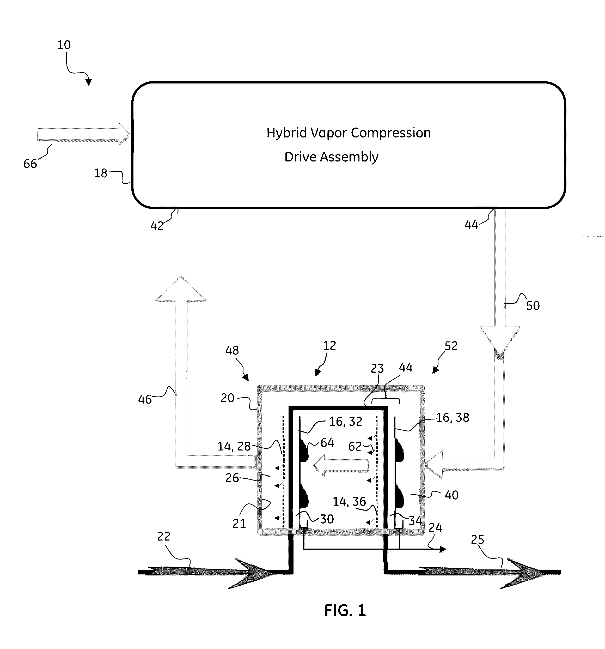
[0019]FIG. 1 is a schematic diagram of an exemplary membrane distillation system 10 including a hybrid vapor compression drive assembly in accordance with an exemplary embodiment. For the illustrated example, the membrane distillation system 10 comprises a membrane distillation (MD) module 12 including a plurality of MD membranes 14 and a plurality of heat transfer films 16 arranged in alternating or interleaved configuration. The membrane distillation system 10 further includes a hybrid vapor compression drive assembly 18 in fluidic communication therewith. The use of a hybrid vapor compression drive assembly 18 provides a promising alternative to purely sensible heat driven multi effect membrane distill...


PUM


Abstract

A membrane distillation drive assembly including a vapor compressor, a steam expander and a prime mover, wherein a total vapor compressor load is shared between the steam expander and the prime mover. The membrane distillation drive assembly configured for driving a membrane distillation system further comprising a MD module disposed within an object and configured to receive an input feed stream and produce an output product flow stream. The vapor compressor configured to receive an input flow of low pressure steam and produce a compressed output flow, the steam expander configured to receive an input flow of high pressure steam and produce an expanded output flow. The compressed output flow and the expanded output flow provide an output flow of intermediate pressure steam to the MD module. The prime mover is coupled to the vapor compressor by one of a mechanical or electrical coupling.

Description

BACKGROUND[0001]The present disclosure relates generally to membrane distillation technology. More particularly, this disclosure relates to membrane distillation systems and a novel vapor compression drive assembly for a membrane distillation system.[0002]Membrane distillation (MD) is a thermally driven separation process that may commonly be employed to de-ionize or desalt a water source. In addition, membrane distillation may be used during the processing of foods, the removal of organic materials from water sources and also, but not limited to, the production processes of ethanol, cellulosic ethanol, farnesene and various bio-chemicals, such as butanol or the like. The premise behind membrane distillation is a vapor pressure difference induced by a temperature gradient created across a microporous membrane that separates vapor-liquid / liquid-liquid phases in equilibrium. Of particular interest in the membrane distillation process as an emerging technology is the means by which the...

Claims


Application Information

Patent Timeline
IPC IPC(8): C02F1/44B01D61/36
CPCC02F1/447B01D61/364B01D61/366B01D61/368B01D2313/243C02F2103/08B01D2319/025B01D2313/38C02F2101/10B01D2313/24B01D2313/246Y02A20/124
Inventor PEREIRA, RICARDO HERNANDEZRUETTEN, JENSCINELLI, BERNARDO ALVESCOSTA, ANA CAROLINA MIRANDA
Owner GENERAL ELECTRIC CO
Why Eureka
Try Eureka