
Optical analyzer, optical analyzing method and sample preparation device

an analyzer and optical analysis technology, applied in the field of optical analyzers, can solve the problems of reducing the precision of the analysis, reducing the accuracy of the analysis, so as to improve the accuracy and reliability of the results

Active Publication Date: 2016-10-13
GRAINSENSE
View PDF7 Cites 9 Cited by
  • Summary
  • Abstract
  • Description
  • Claims
  • Application Information

AI Technical Summary

Benefits of technology

This patent aims to improve the accuracy and reliability of optical measurements in agricultural samples by relying on both the optical filtering by the sample and the hidden mass available for measurement. Additionally, the invention seeks to reduce the amount of sample needed for reliable measurement results and to provide a handheld optical analyzer that can be taken to agricultural production areas to eliminate waiting time and transportation of samples.

Problems solved by technology

Not available so far, however, except for moisture, are rugged and relatively low-cost analyzers for widespread use.
Generally speaking, when measuring granular samples the transmissive methods bear the problem of accidental background noise originated in unfavorable sample element distributions, whereas the reflective methods bear the problem that only a minimum of the sample mass is taken into account.
This effect is not as problematic with transmissive methods, however, there a full absorption may take place due to the thickness of the sample resulting in nearly zero transmission or total absorption leaving no measurable signal.
In many reflective measurements, the bulk of the sample mass is hidden due to the limited light penetration depth underneath the illuminated surface.
However, the problem remains to generate a reasonable randomization of the samples in order not to jeopardize the reliability of the spectrally filtered response.

Method used


Image

  • Optical analyzer, optical analyzing method and sample preparation device
  • Optical analyzer, optical analyzing method and sample preparation device
  • Optical analyzer, optical analyzing method and sample preparation device

Examples


Embodiment Construction

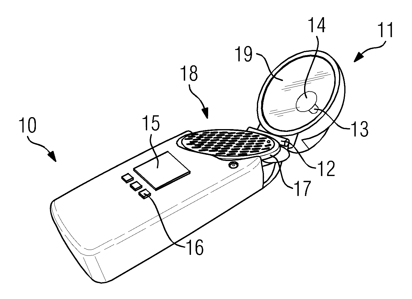
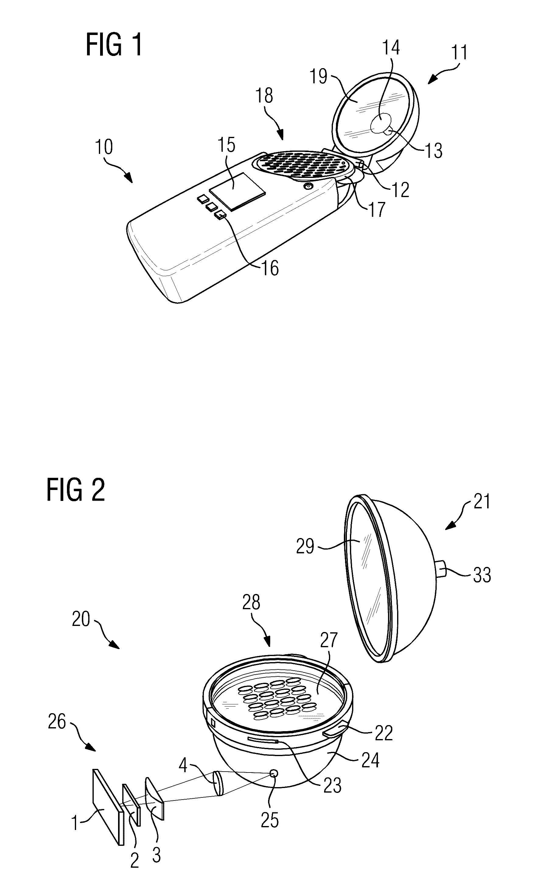
[0094]FIG. 1 shows a handheld optical analyzer 10 with an optically integrating cavity based on two half-spheres 11, whereas the half-sphere 11 is connected to the optical analyzer 10 using a hinge 12. The sample holder 17 is integrated into the housing of the optical analyzer 10. The second half-sphere below the sample holder 17 (not visible) is also integrated into the optical analyzer 10 without user access to avoid contamination. The sphere has an inside diameter of 80 millimeters.

[0095]Alternatively the sample holder 17 may be removable to allow collecting samples directly into the holder 17 by inserting it into a heap of sample elements and then place it inside the sphere.

[0096]The sample elements, for example, kernels of a certain grain are spread into the indentations 18. At least about 80% of them should be filled in order to generate an acceptable signal-to-noise ratio. Ideally there are indentations 18 for about 80 sample elements. The sphere might be filled by putting th...


PUM

PropertyMeasurementUnit
timeaaaaaaaaaa
optical wavelengthsaaaaaaaaaa
weightaaaaaaaaaa

Abstract

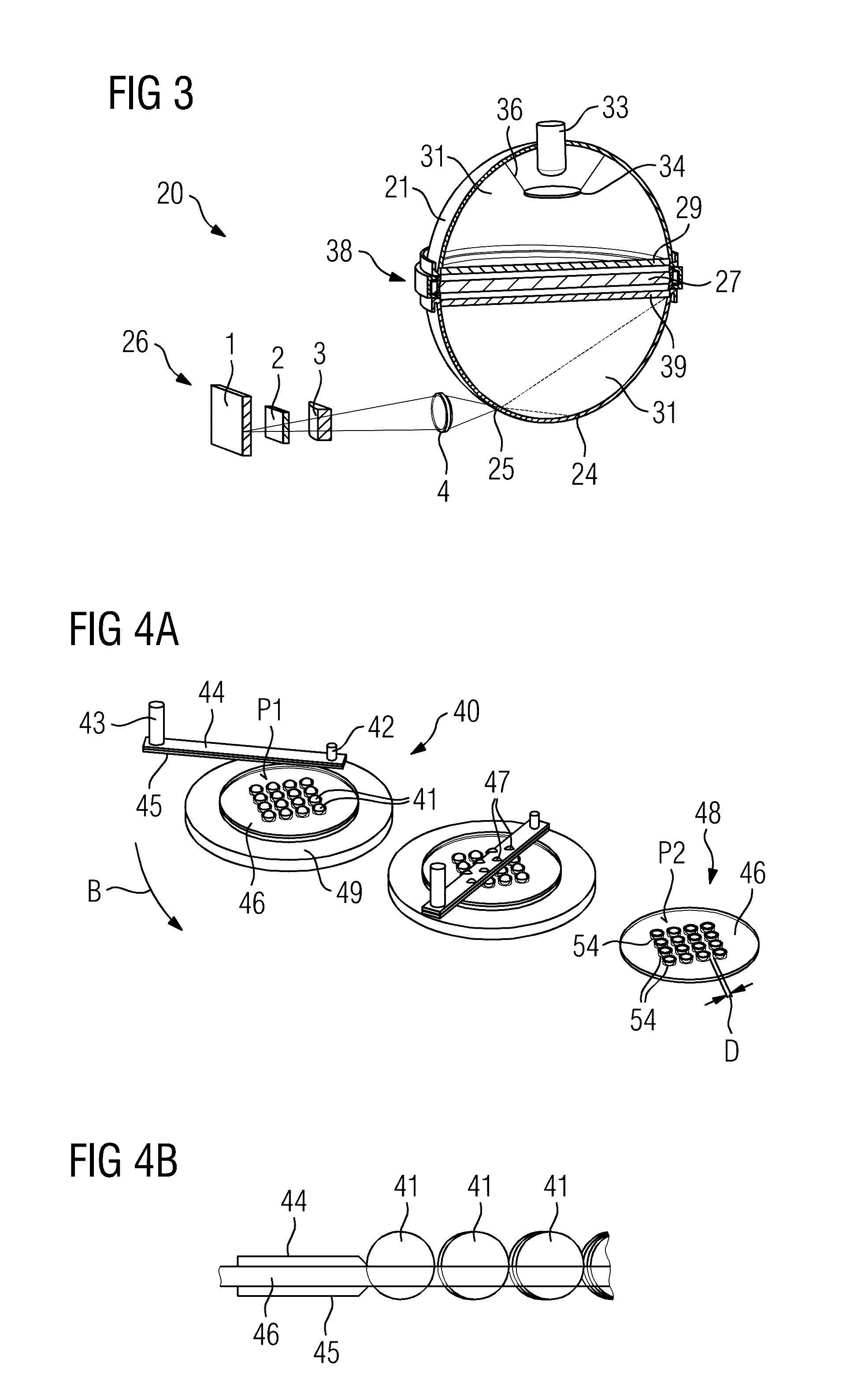
Optical analyzer (10,50,60) comprises an optically integrating cavity (20), the optically integrating cavity (20) formed by at least one optical light diffusing wall (31) and adapted to contain a sample of a solid agricultural product, the sample consisting of one or more sample elements (41,48), a light source (13,33), emitting light into the optically integrating cavity (20), whereas the at least one optical light diffusing wall (31) is utilized to convert emitted light to diffused light, whereas the sample at least partially or completely converts the diffused light to spectrally filtered light, and a spectral sensor (26). The sample is confined in the optically integrating cavity (20) while the spectral sensor (26) is being exposed to the spectrally filtered light. Patent application has independent claims also for optical analyzing method and sample preparation device.

Description

FIELD OF INVENTION[0001]The invention relates to an optical analyzer, in particular handheld analyzer, and corresponding method to analyze granular agricultural samples, such as grain, for contained substances whose concentrations are relevant for agricultural decision taking and planning, such as moisture or protein. Furthermore, the invention relates to a sample preparation device for conditioning agricultural samples for the optical analysis.BACKGROUND OF INVENTION[0002]From the prior art many methods are known to qualitatively or quantitatively investigate the ingredients of agricultural products, in particular grain. In order to figure out the value of a growing, harvested, or stored crop and to decide upon possible actions it is important to know about the ingredients.[0003]Today, samples are taken and sent to specialized laboratories for analysis. Not available so far, however, except for moisture, are rugged and relatively low-cost analyzers for widespread use. The greatest ...

Claims


Application Information

Patent Timeline
Patent Type & Authority Applications(United States)
IPC IPC(8): G01N21/359G01N21/3563G01N1/28
CPCG01N21/359G01N2201/0221G01N21/3563G01N1/28G01N21/3554G01N2201/0632G01N21/59
Inventor MARBACH, RALF
Owner GRAINSENSE
Learn More