Laser scanning observation device and laser scanning method

a laser scanning and observation device technology, applied in the field of laser scanning observation devices and laser scanning methods, can solve the problems of deterioration in the quality of image data to be acquired, affecting the degree of aberration, and the technique failing to deal with the case, so as to achieve the effect of high precision observation

Inactive Publication Date: 2016-10-13
SONY CORP
View PDF4 Cites 41 Cited by
  • Summary
  • Abstract
  • Description
  • Claims
  • Application Information

AI Technical Summary

Benefits of technology

[0018]According to the embodiments of the present disclosure as described above, it is possible to perform higher precision observation. Note that the advantages described above are not necessarily intended to be restrictive, and any other advantages described herein and other advantages that will be understood from the present disclosure may be achievable, in addition to or as an alternative to the advantages described above.

Problems solved by technology

In particular, when laser light passes through the window having a cylindrical surface, aberration may occur even on the optical axis (especially, astigmatism), resulting in deterioration in the quality of image data to be acquired.
In the technique disclosed in Non-Patent Literature 2, the aberration is corrected using the shape of a mirror to improve the image quality, but the technique fails to deal with the case in which the degree of aberration is changed by a change in the depth of observation as described above.
In this way, in the endoscopes known in the art, it is difficult to achieve the enhancement of safety by providing a window having the predetermined thickness while using an objective lens having relatively large NA and, at the same time, to achieve the observation with high accuracy by reducing the influence of aberration.

Method used


Image

  • Laser scanning observation device and laser scanning method
  • Laser scanning observation device and laser scanning method
  • Laser scanning observation device and laser scanning method

Examples


first embodiment

2. FIRST EMBODIMENT

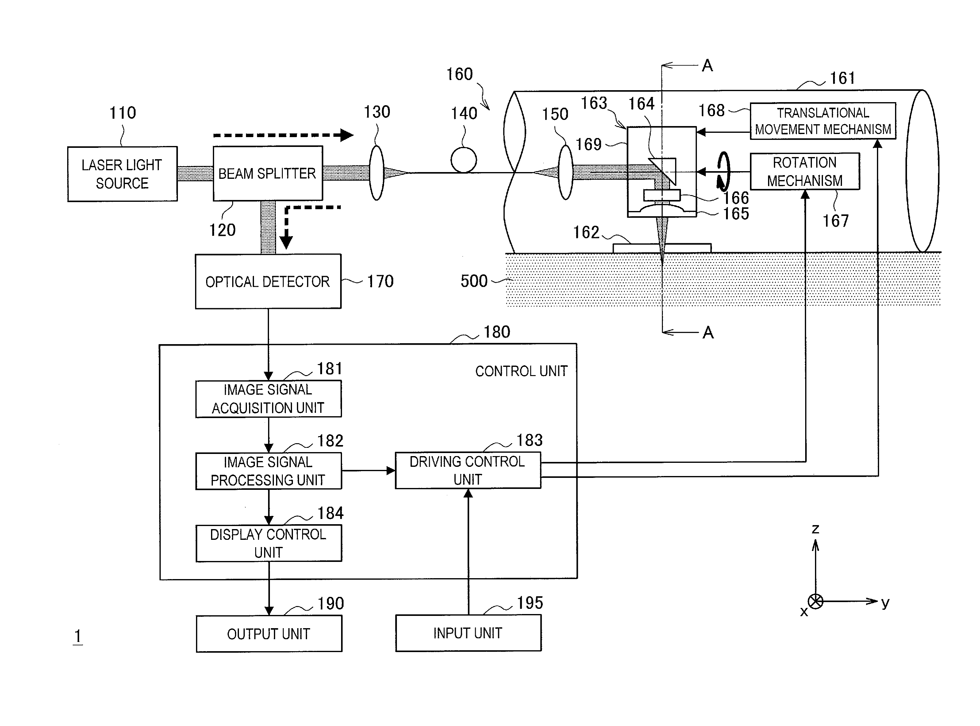
[0108]First, a configuration example of a laser scanning endoscopic device 1 according to a first embodiment of the present disclosure will be described with reference to FIGS. 2 and 3. FIG. 2 is a schematic diagram illustrating one configuration example of the laser scanning endoscopic device 1 according to the first embodiment of the present disclosure. FIG. 3 is a schematic diagram illustrating the configuration of a scanning unit illustrated in FIG. 2. In the following drawings including FIGS. 2 and 3, a supporting member supporting each constituent member included in the laser scanning endoscopic device according to embodiments of the present disclosure is not illustrated. Also, though the detailed description will be omitted, constituent members are assumed to be appropriately supported by various supporting members such that propagation of laser light and driving of the constituent members to be described below do not interfere.

[0109]Referring to FIG. 2, th...

second embodiment

3. SECOND EMBODIMENT

[0175]Next, one configuration example of a laser scanning endoscopic device according to a second embodiment of the present disclosure will be described with reference to FIG. 4A. FIG. 4A is a schematic diagram illustrating one configuration example of the laser scanning endoscopic device according to the second embodiment of the present disclosure.

[0176]Referring to FIG. 4A, a laser scanning endoscopic device 2 according to the second embodiment includes a laser light source 110, a beam splitter 120, an optical modulator 230, an optical fiber bundle 240, optical fiber light-guiding lenses 130 and 150, an endoscope 160, an optical detector 170, a control unit 280, an output unit 190, and an input unit 195. For the sake of simplicity, only a configuration related to acquisition of image data by laser scanning is illustrated in FIG. 4A among the functions of the laser scanning endoscopic device 2. Here, the laser scanning endoscopic device 2 may further have variou...

modification examples

4. MODIFICATION EXAMPLES

[0192]Next, several modification examples of the laser scanning endoscopic devices 1 and 2 according to the first and second embodiments of the present disclosure will be described. Also, in the description of the following modification examples of the first and second embodiments, the laser scanning endoscopic device 1 according to the first embodiment will be mainly exemplified for the description. However, configurations of the modification examples to be described below are also applicable to the laser scanning endoscopic device 2 according to the second embodiment. A similar configuration to the modification example illustrated below may be applicable to the laser scanning probe and the laser scanning microscopic device according an embodiment, which will be described below in item 6-2 (Laser scanning probe) and item 6-3 (Laser scanning microscopic device), respectively.

[0193](4-1. Configuration in Which Scanning Unit Includes Plurality of Objective Lens...


PUM


Abstract

Provided is a laser scanning observation device including: a window unit provided in a partial area of a casing and configured to be in contact with or close to an observation target; an objective lens configured to collect laser light on the observation target through the window unit; an optical path changing element configured to change a direction of travel of the laser light guided within the casing toward the window unit; an astigmatism correction element provided in a front stage of the window unit and configured to correct astigmatism occurring upon the collection of the laser light on the observation target; and a rotation mechanism configured to allow at least the optical path changing element to rotate about a rotation axis perpendicular to a direction of incidence of the laser light on the window unit to scan the observation target with the laser light.

Description

TECHNICAL FIELD[0001]The present disclosure relates to a laser scanning observation device and a laser scanning method.BACKGROUND ART[0002]As technologies for observing objects at a high resolution, there are laser scanning microscopic devices. The laser scanning microscopic devices can acquire various kinds of information regarding objects as 2-dimensional or 3-dimensional image data by applying laser light to the objects and detecting the intensity of its transmitted light, backscattered light, fluorescent light, Raman-scattered light, various kinds of light produced due to a nonlinear optical effect, or the like while scanning the objects with the laser light. In recent years, the technology using such a laser scanning microscopic device has been applied to a probe in contact with the body surface of a subject (a patient) or an endoscope inserted into the body cavity of a subject, thereby observing the body tissue of the subject (patient) at higher resolution.[0003]In the field o...

Claims


Application Information

Patent Timeline
Patent Type & Authority Applications(United States)
IPC IPC(8): G01Q60/20G02B23/24G02B27/28G02B27/00G02B21/00
CPCG01Q60/20G02B27/0068G02B27/0031G02B23/2423G02B21/006G02B21/0076G02B27/283G02B21/0072G02B26/10A61B1/00172A61B1/00177G02B23/2469G02B23/26
Inventor ITO, TERUMASAFUKUMOTO, ATSUSHIMAEDA, FUMISADACHUBACHI, HIDEYAHIRONO, YU
Owner SONY CORP
Why Eureka
Try Eureka