Method of determining an islanding solution for an electrical power system

a technology of electrical power system and solution, applied in the field of method, can solve the problems of weak connection based approaches, which can only ever be used, and is simply not able to capture the complexity involved, and achieve the effect of computation

Inactive Publication Date: 2016-10-13
UNIV OF MANCHESTER
View PDF7 Cites 18 Cited by
  • Summary
  • Abstract
  • Description
  • Claims
  • Application Information

AI Technical Summary

Benefits of technology

[0029]Essentially, the weak area approach identifies the areas of the power system in which the appropriate system splitting solutions are most likely to occur based on the dynamic properties of the system. An advantage of identifying these weak areas and only considering the transmission lines within them when determining the final splitting solution is that the size of the searching space is significantly reduced. Consequently, the time necessary to find the optimal final splitting solution is also significantly reduced.
[0063]Determining the islanding solution by only considering power flows over connections represented by edges located in weak areas significantly decreases the number of connections that are considered when determining the islanding solution. Therefore, the speed with which the islanding solution can be determined is significantly increased.

Problems solved by technology

This is in contrast to existing weak connections based approaches, which can only ever be used to optimise the islanding solution for a single objective function.
This advantage is of critical importance because it is simply not possible to capture the complexity involved in the intentional controlled islanding of practical power systems through a single objective function.

Method used


Image

  • Method of determining an islanding solution for an electrical power system
  • Method of determining an islanding solution for an electrical power system
  • Method of determining an islanding solution for an electrical power system

Examples


example

[0151]System and Graph Properties

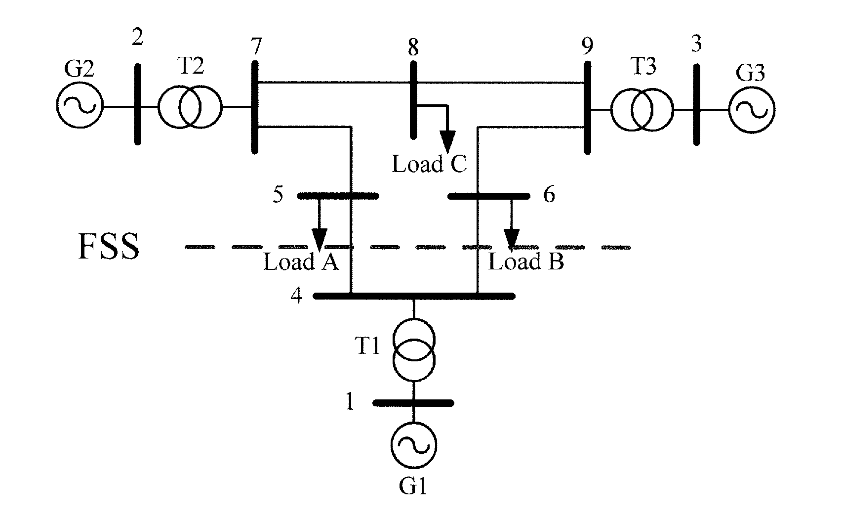
[0152]The nine-bus test system example shown in FIG. 1 is used to detail the embodiment. The test system can be found in P. M. Anderson and A. A. Fouad, Power System Control and Stability, 2nd ed. New York: IEEE Press, 2003, which is incorporated herein by reference.

[0153]Identifying Generator Coherency and WAs

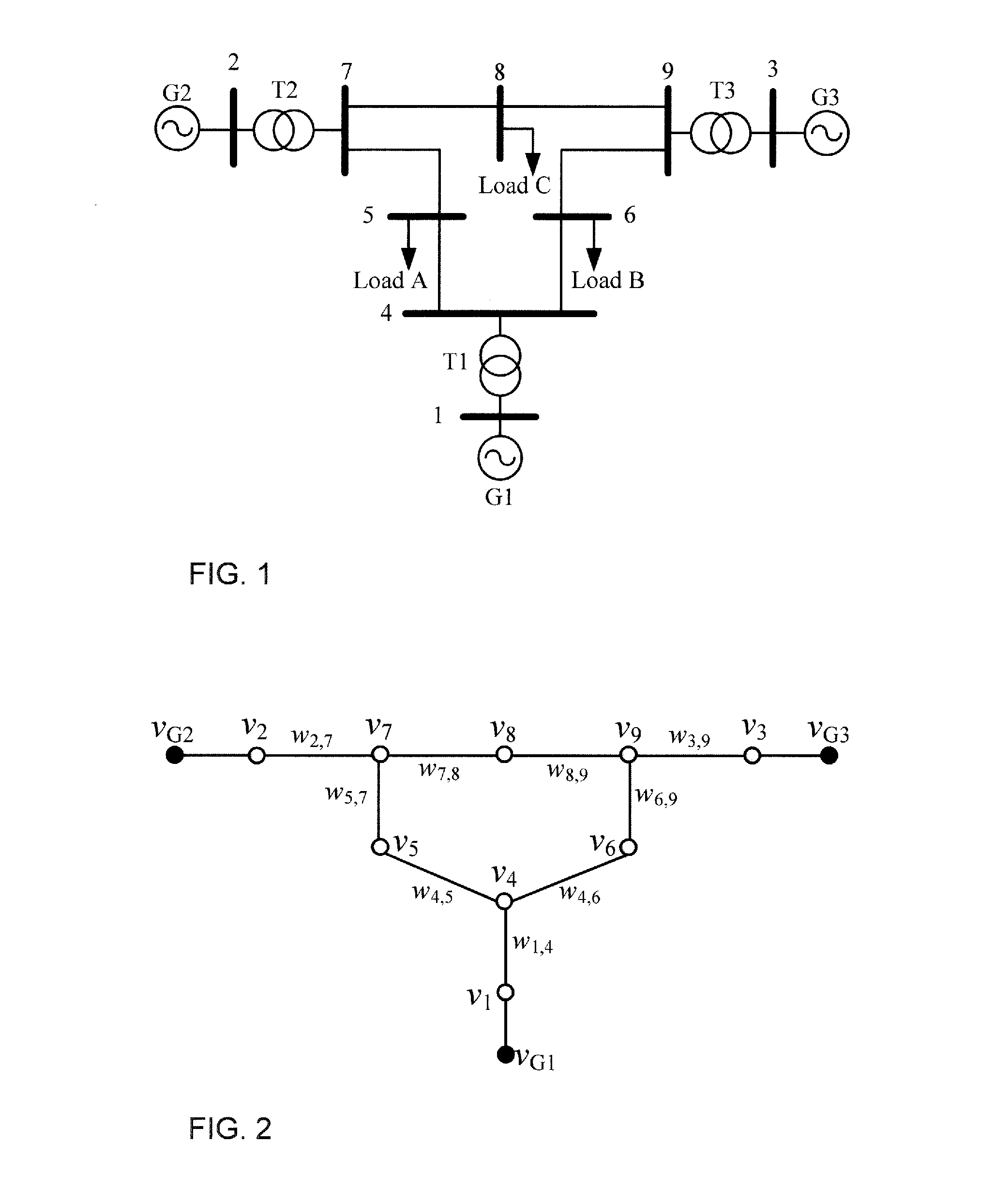
[0154]The dynamic properties of the entire power system are described using equation (4). This model can be represented using the dynamic graph illustrated in FIG. 2.

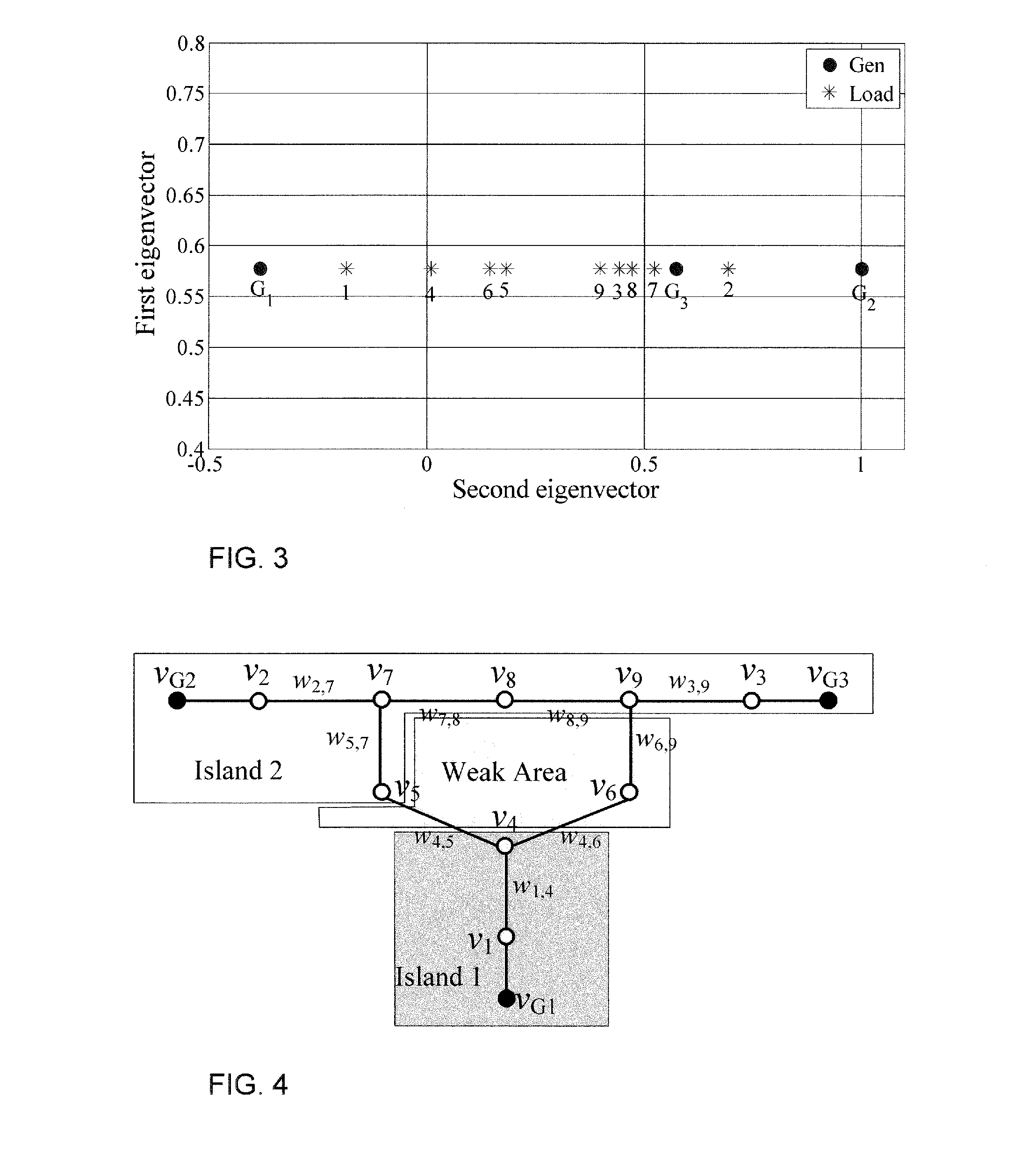
[0155]The r eigenvectors associated with the r smallest eigenvalues are calculated as they describe the contribution of each generator to each mode (eq. equation (12) is solved), as shown in the following table.

First eigenvectorSecond eigenvectorG10.5774−0.3825G20.57741.0000G30.57740.5729

[0156]Gaussian elimination is then applied to determine the reference generators. The results of the Gaussian elimination reflect that the two reference generators are G2 and G1, as shown in the fo...


PUM


Abstract

Method of determining an islanding solution for a power system comprising representing synchronising coefficients between generators and couplings between load buses and generators of the power system as a dynamic graph, calculating eigenvalues and eigenvectors of a graph laplacian describing the synchronising coefficients, identifying reference generators, calculating eigenvectors describing dynamic coupling between load buses and reference generators, using the synchronising coefficient and dynamic coupling eigenvectors to determine proximities between reference generators and other buses, assigning other buses to reference generators according to the proximities, selecting a threshold, identifying buses in weak-areas by using the threshold to identify buses having a proximity to their reference generator sufficiently similar to their proximity to another reference generator, determining the islanding solution by selecting connections to disconnect to split the power system into two or more islands based on an analysis of power flows only on connections to, or between, buses in weak-areas.

Description

FIELD OF THE INVENTION[0001]The present invention relates to a method of determining an islanding solution that separates an electrical power system comprising a plurality of generator buses and load buses into r electrically isolated islandsBACKGROUND OF THE INVENTION[0002]An electrical power system is a network of electrical components used to generate, transmit and consume electrical power. An electrical power system includes generators, which generate the electrical power and supply the electrical power to the electrical power system, loads, which use the electrical power in the electrical power system, and transmission and distribution systems that transmit and distribute the electrical power from the generators to the loads.[0003]Electrical power systems can be used to distribute electrical power from generators to different loads, such as different residential, business or industrial premises, in a specific geographical area. These geographical areas may range in size from a ...

Claims


Application Information

Patent Timeline
Patent Type & Authority Applications(United States)
IPC IPC(8): H02J3/40H02J3/38
CPCH02J3/40H02J2003/388H02J3/381H02J3/38H02J3/388H02J2203/20Y02E60/00Y04S40/20
Inventor TERZIJA, VLADIMIRTORTOS, JAIRO QUIROSWALL, PETER
Owner UNIV OF MANCHESTER
Why Eureka
Try Eureka