Power generation systems

Inactive Publication Date: 2016-10-13
POWER PARTNERS INT LLC
View PDF1 Cites 6 Cited by
  • Summary
  • Abstract
  • Description
  • Claims
  • Application Information

AI Technical Summary

Problems solved by technology

As energy sources based on fossil fuels become increasingly expensive, the world has turned to renewable energy sou

Method used


Image

  • Power generation systems
  • Power generation systems
  • Power generation systems

Examples


Embodiment Construction

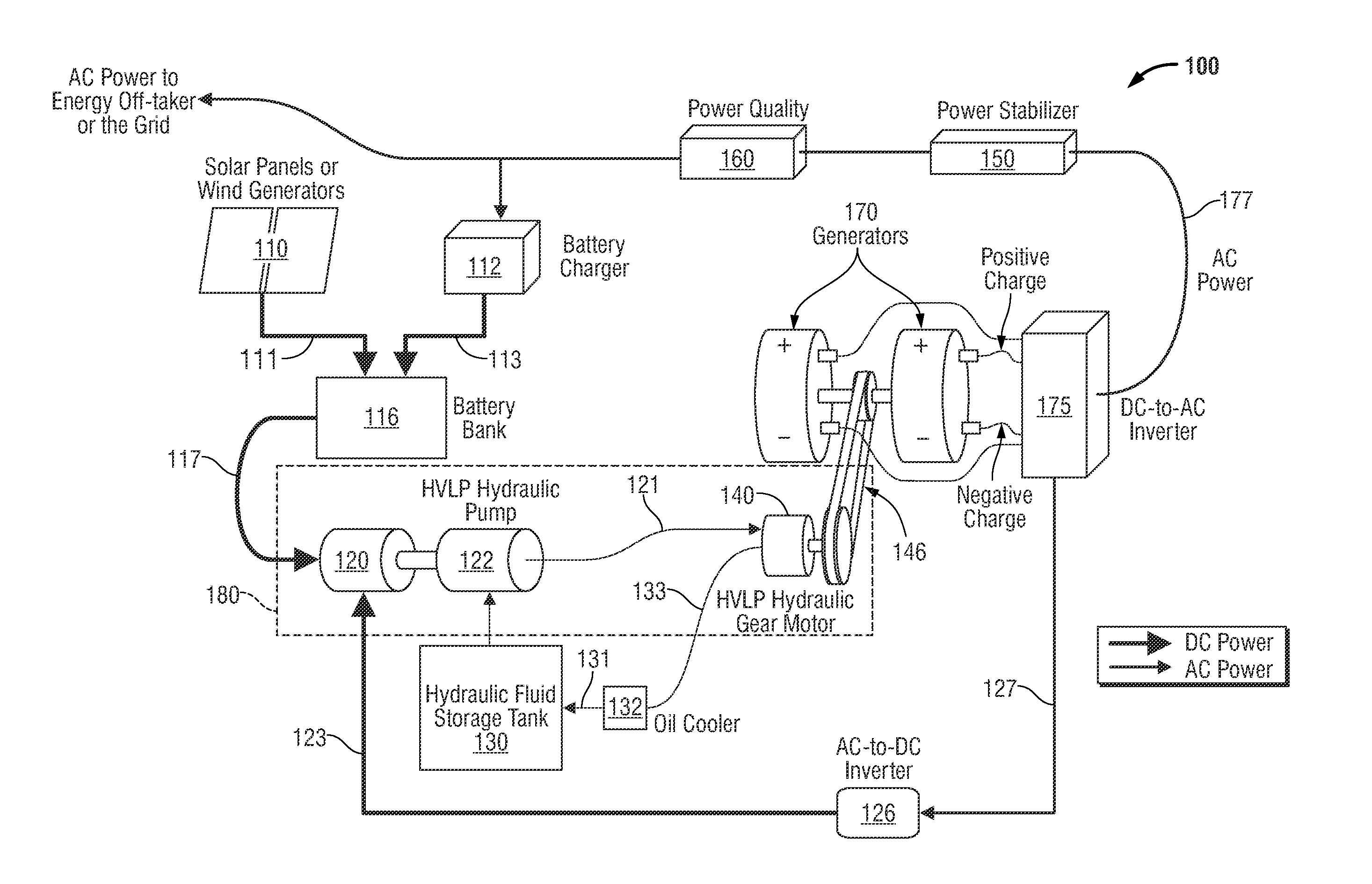
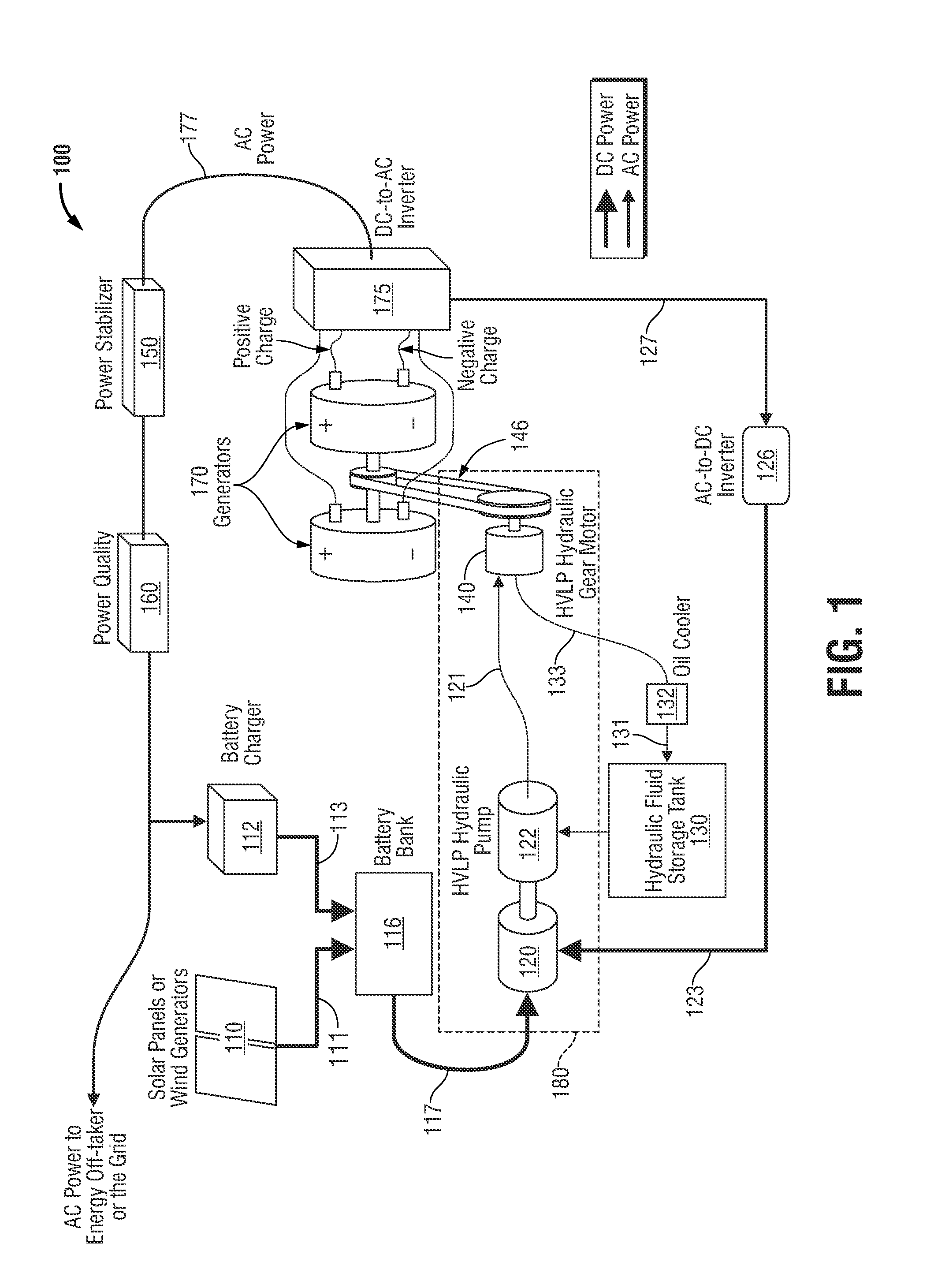
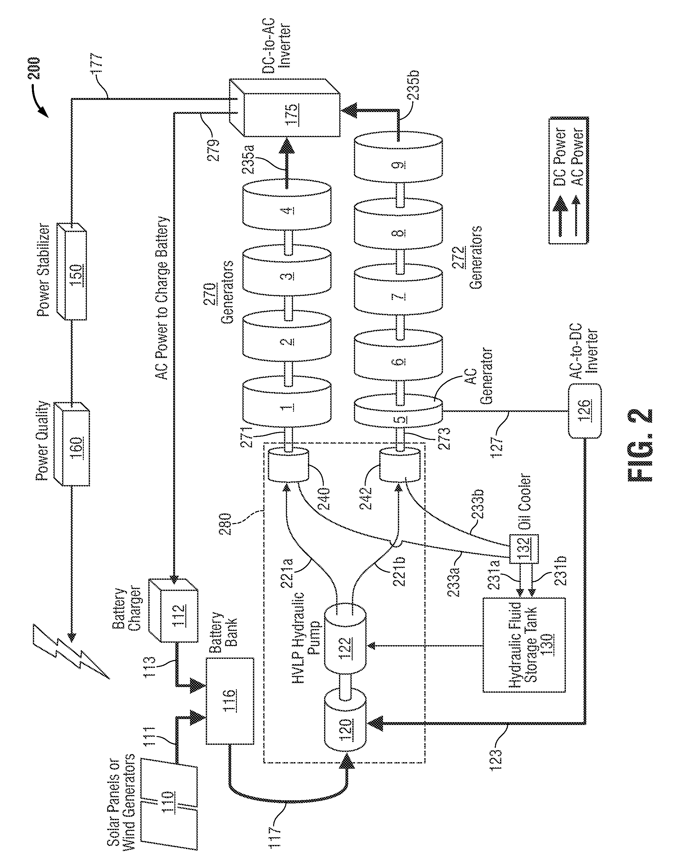
[0013]Hereinafter, embodiments of a power generation system are described with reference to the accompanying drawings. Like reference numerals may refer to similar or identical elements throughout the description of the figures.

[0014]This description may use the phrases “in an embodiment,”“in embodiments,”“in some embodiments,” or “in other embodiments,” which may each refer to one or more of the same or different embodiments in accordance with the present disclosure.

[0015]As it is used in this description, “transmission line” generally refers to any transmission medium that can be used for the propagation of signals from one point to another.

[0016]Various embodiments of the present disclosure provide a power generation system together with solar panels (or wind generators, or other renewable energy source) that preferably provides power twenty-four hours a day for as long as necessary. Embodiments of the presently-disclosed power generation system may provide alternating current (A...


PUM


Abstract

The present disclosure is directed to several embodiments or variations of a power generation system. Several of these variations use the same power generators and also include one or more prime movers that supply mechanical power to the generators. In a first embodiment of the power generation system, two single drive through-shaft generators adapted to produce electric power are configured to be driven by a common prime mover. In a second, alternative embodiment of the power generation system, a plurality of generators is arranged into first and second generator groups. Each of the first and second generator groups is operably associated with an independent motor, which allows the power output to be controlled via adjustment to the applied power of the independent motors.

Description

CROSS-REFERENCE TO RELATED APPLICATIONS[0001]Not Applicable.STATEMENT RE: FEDERALLY SPONSORED RESEARCH / DEVELOPMENT[0002]Not ApplicableBACKGROUND OF THE INVENTION[0003]1. Technical Field of the Invention[0004]The present disclosure relates generally to a power generation system for the generation of electricity. More particularly, the present disclosure relates to a power generation system together with solar panels or wind generators that is capable of operating continuously.[0005]2. Discussion of the Related Art[0006]Electric power can be generated from coal, oil, gas, wind, ground heat, and solar energy. As energy sources based on fossil fuels become increasingly expensive, the world has turned to renewable energy sources. Although solar energy comprises a very abundant source, conversion to useable forms of energy can be expensive. An increasing demand for electric power continues to push the need for innovative new ways to generate electric power. There is a continuing need for ...

Claims


Application Information

Patent Timeline
IPC IPC(8): H02K47/04H02J5/00
CPCH02K47/04H02K53/00Y10S74/09H02J5/00H02J3/32H02J2300/24H02J3/381Y02E10/56Y02E10/72Y02E70/30
Inventor REGIER, STEPHENHILL, ALBERT S.
Owner POWER PARTNERS INT LLC
Why Eureka
Try Eureka