

Composite devices and methods for providing protection against traumatic tissue injury
a technology of traumatic tissue injury and composite devices, which is applied in the direction of protective garments, helmet covers, helmet covers, etc., can solve the problems of exacerbate injury, equipment failure, design flaws, etc., and achieve low coefficient of friction, soft and deformable, and mitigate injury
- Summary
- Abstract
- Description
- Claims
- Application Information
AI Technical Summary
Benefits of technology
Problems solved by technology
Method used
Image

Examples
example 4
Embodiment of Protective Head Gear
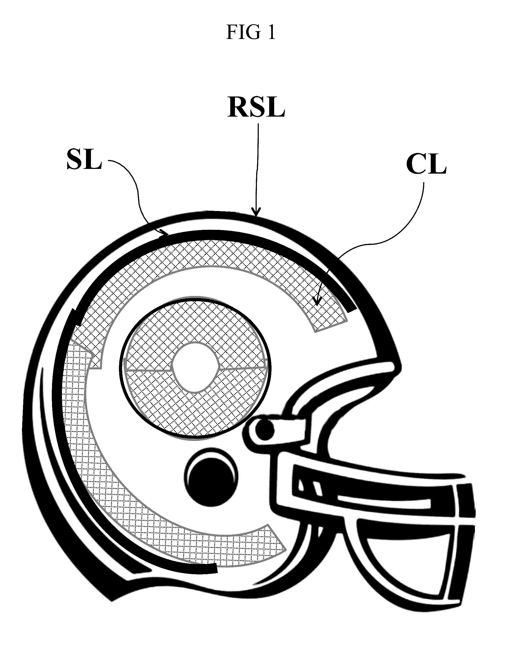
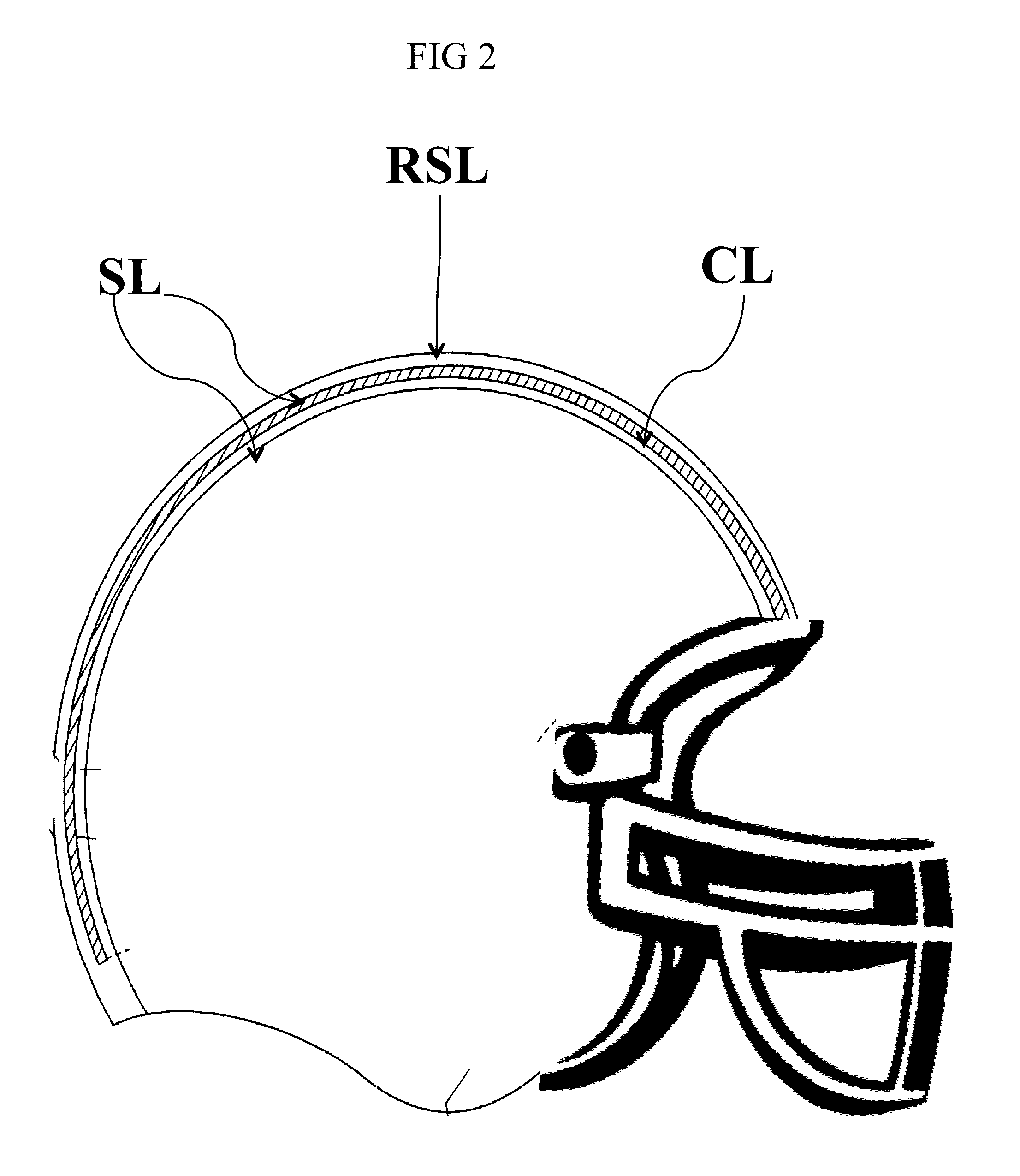
[0136]In another exemplary embodiment according to this disclosure, a protective head guard is provided. The design is particularly well suited for protecting against injury that arises from indirect impacts. The head guard includes:
[0137]an conforming pliable helmet that allows a close fit to the wearer's head;
[0138]at least a first slip component layer comprising one or more lubricious components, provided in a matrix, or free flowing, or in sections, or combinations of these;
[0139]at least a first crush component layer situated adjacent to the slip component layer, the crush component formed of a three dimensional array that comprises material and dimensional properties selected to dissipate linear impact loads ranging from 20 to 1000 N / m2 and rotational / angular impact loads ranging from 20 to 300 kg m2 / s2 of torque;
[0140]wherein the slip component and crush component layers are affixed to the pliable conforming helmet;
[0141]and wherein, the over...
example 5
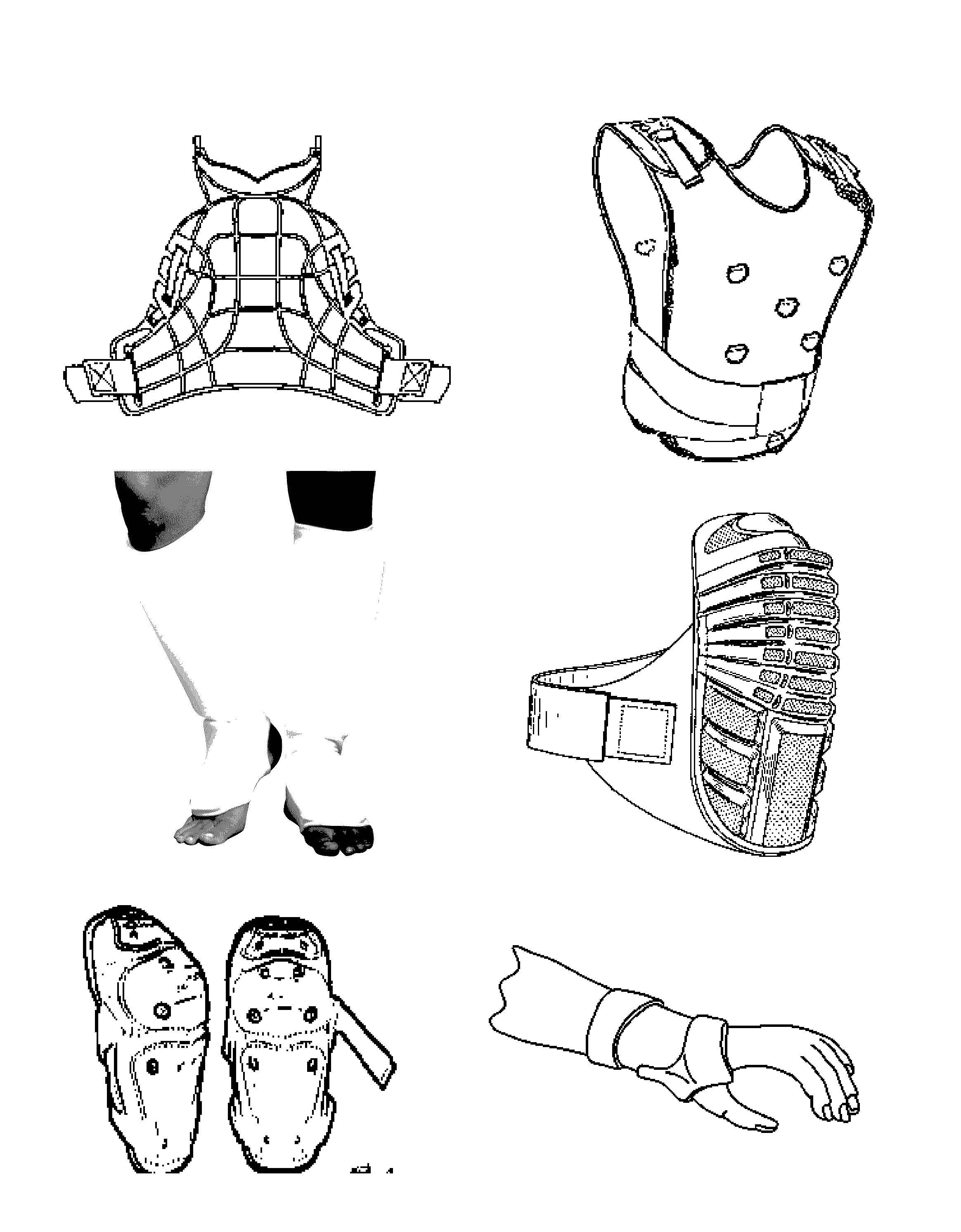
Embodiment of Protective Chest Gear
[0149]In another exemplary embodiment according to this disclosure, a protective chest guard is provided. The design is particularly well suited for protecting against injury that arises from both direct and indirect impacts. The chest guard includes:
[0150]a flexible harness including shoulder straps and a securement mechanism;
[0151]a guard body engagable with the harness and sized to cover at least a portion of the chest area, the guard body comprising at least one crush layer component formed of a three dimensional array that comprises material and dimensional properties selected to dissipate linear impact loads ranging from 20 to 900 N / m2;
[0152]wherein the guard body is engaged with the harness in a manner that allows free movement of the wearer's arms relative to the guard body; and
[0153]wherein the overall structure of the chest guard is consistent with chest guards and chest guard apparel in the conventional art, being lightweight, the guard ...
example 6
Embodiment of Protective Gear for Extremities
[0160]In another exemplary embodiment according to this disclosure, a protective guard for an extremity, such as a knee, shin, elbow, groin, is provided. The design is particularly well suited for protecting against injury that arises from direct impacts. The guard includes:
[0161]a guard body engagable sized to cover at least a portion of the chest area, the guard body comprising on its outer surface a resilient outer shell that forms a shield component layer that is thin, lightweight and rigid, and has an outer surface that comprises a friction mitigating layer at least a portion of which has a low coefficient of friction (from less than to approximately equal to the coefficient of friction of ice at 0 degrees C.), the shield component layer having a hardness and brittleness selected for initially receiving and resisting high impact prior to fracture, and due to the low friction surface is capable of slipping when in contact with another...
PUM
 Abstract
Description
Claims
Application Information