Belt Drive Wave Energy Plant

a technology of belt drive and power plant, which is applied in the direction of buoys, floating buildings, anchorage arrangements, etc., can solve the problems of never intended for off-shore use, difficult and costly regular service and maintenance, etc., and achieve the effects of improving, reliable and robust drive system, improving, and improving efficiency and reliability

a technology of belt drive and power plant, which is applied in the direction of buoys, floating buildings, anchorage arrangements, etc., can solve the problems of never intended for off-shore use, difficult and costly regular service and maintenance, etc., and achieve the effects of improving, reliable and robust drive system, improving, and improving efficiency and reliability

US20160305395A1Active Publication Date: 2016-10-20WEPTOS

Image

  • Belt Drive Wave Energy Plant
  • Belt Drive Wave Energy Plant
  • Belt Drive Wave Energy Plant

Examples


Embodiment Construction

[0056]In the following detailed description, a wave power plant according to the invention will be described reference to preferred embodiments.

[0057]Wave power plants are also referred to as wave energy converters.

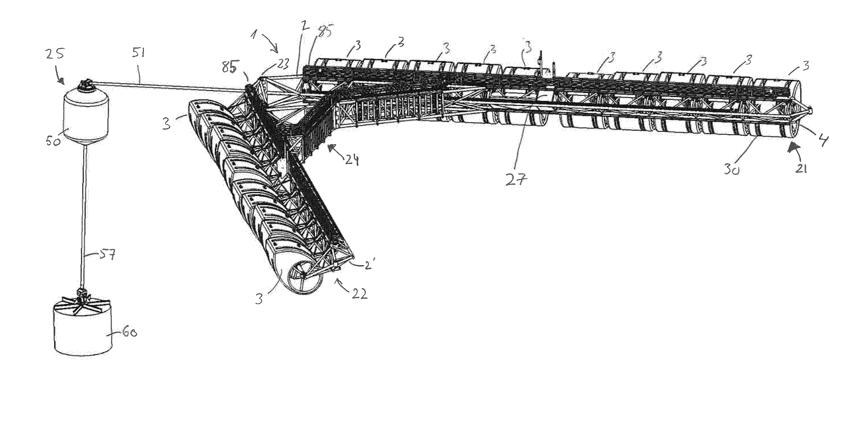
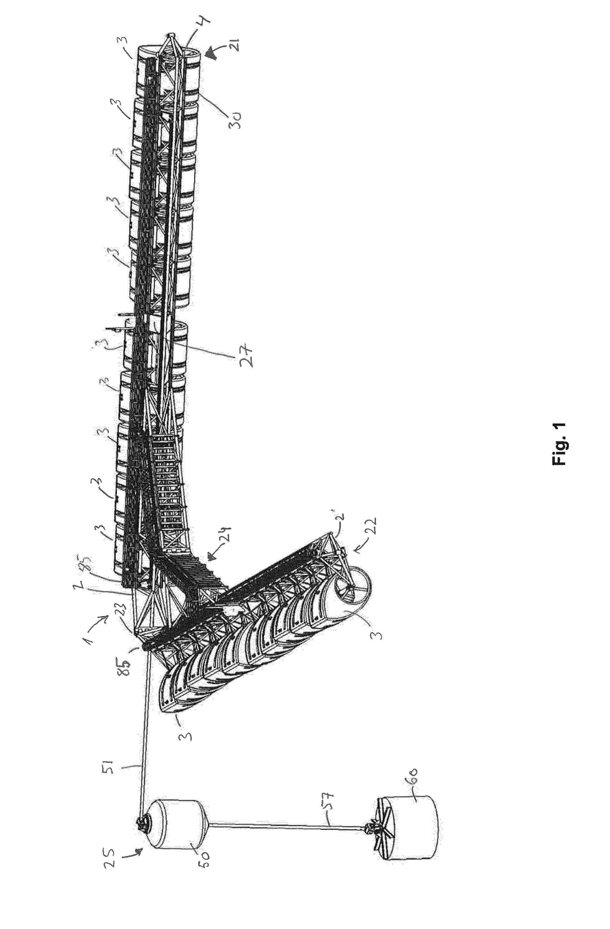
[0058]FIG. 1 shows an embodiment of a wave power plant 1 according to the present invention. The wave power plant 1 is a floating structure. The shown wave power plant 1 has twenty rotors in the form of rocking rotors 3 that—during use—are all partially immersed into the water surface area. The rocking rotors 3 are each arranged on a rotor shaft 4.

[0059]Each of the rocking rotors 3 has a buoyancy and a shape which is asymmetrical about the rotor shaft 4 to the effect that, when waves hit the rocking rotor 3, it is forced to rotate first in one direction about the rotor shaft 4 and hence to rotate the rotor shaft, and then in the reciprocal direction, as the wave passes the rocking rotor 3. Thus, the rocking rotor 3 performs a rocking motion relative to a frame constructio...


PUM


Abstract

A wave power plant (1) comprising: a frame construction (2, 2′), a plurality of rocking rotors (2) arranged on the frame construction (2, 2′) on at least on rotor axis (4), a drive axis (30) connected to a generator and journaled in said frame construction (2, 2′); and at least one belt drive connection (40) arranged between the rotor axis (4) and the drive axis (30) for each rocking rotor (3).

Description

BACKGROUND OF THE INVENTION[0001]The present invention relates to a wave power plant for extracting power from the wave movement of a water surface area, the wave power plant being of a type specially suitable for off-shore locations. The invention further relates to a wave energy plant having a plurality of rotors, and which is a floating structure mooring from a single point such as a buoy or the like, such that the wave power plant adjusts to the wave direction.STATE OF THE ART[0002]Today, many different types of wave power plants are known. All share the feature that they utilise the energy which is provided when water is caused to move in a wave movement, and where a wave causes one part of the device to move relative to another part. Such devices typically utilizes that waves will rock one or more rotor devices arranged in the water surface, and examples are known from e.g. GB 1 541 572, U.S. Pat. No. 3,928,967, U.S. Pat. No. 4,300,871 and WO2008132550, disclosing rotors of a ...

Claims


Application Information

Patent Timeline
20 Oct 2016
Publication
US20160305395A1
IPC
F03B13/20; B63B21/50; B63B22/02; B63B35/44
CPC
F03B13/20; B63B35/44; B63B21/50; B63B2035/4466; F05B2220/706; F05B2240/20; B63B22/02; F03B13/1815
Inventors
LARSEN, TOMMY