Compound lens for use with illumination sources in optical systems

a technology of illumination source and compound lens, which is applied in the field of compound lens, can solve the problems of inflexibility of mechanical and optical complexity of conventional compound lens, and inability to capture existing compound lens system, etc., and achieves the effects of providing dimensional stability and structural rigidity, uniform intensity profile, and low cos

Active Publication Date: 2016-10-20
VENTURA MFG1 LLC +1
View PDF7 Cites 4 Cited by
  • Summary
  • Abstract
  • Description
  • Claims
  • Application Information

AI Technical Summary

Benefits of technology

[0011]In another embodiment, the method for manufacturing the compound lens can further include over-molding the compound lens with a lens holding member. The lens holding member can include an opaque thermoset material having a melt-flow temperature below the reflow temperature of the compound lens. The lens holding member can provide dimensional stability and structural rigidity to the compound lens.
[0012]The compound lens can be manufactured to provide highly controlled angled divergent beams with substantially uniform intensity profiles. The com...

Problems solved by technology

The resulting combination of LED light (visible and invisible to the human eye) using conventional compound lenses are necessarily mechanically and optically complex.
Existing compound lens systems require costly mechanical assemblies to capture and align their multiple, individual focusing lenses.
Existing...

Method used


Image

  • Compound lens for use with illumination sources in optical systems
  • Compound lens for use with illumination sources in optical systems
  • Compound lens for use with illumination sources in optical systems

Examples


Embodiment Construction

[0024]The invention as contemplated and disclosed herein includes a compound lens and a related method of manufacture. As set forth in Part I below, the compound lens can include integrally joined lens elements that are formed from an optical grade silicone for an optical emitter. As set forth in Part II below, the related method of manufacture can include injecting a silicone resin molding compound into a mold cavity having the desired shape of the compound lens and optionally over-molding a lens holding member onto the compound lens. As set forth in Part III below, a molding composition is described in connection with the compound lens of Part I and the method of manufacture in Part II.

I. Compound Lens

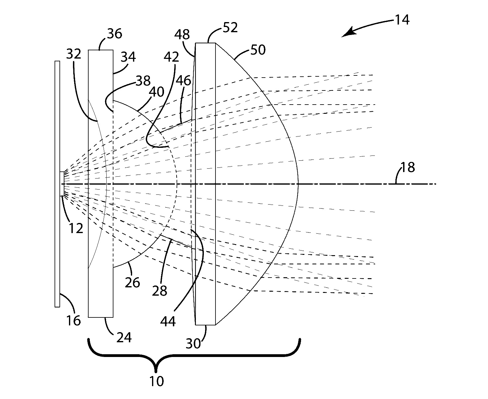
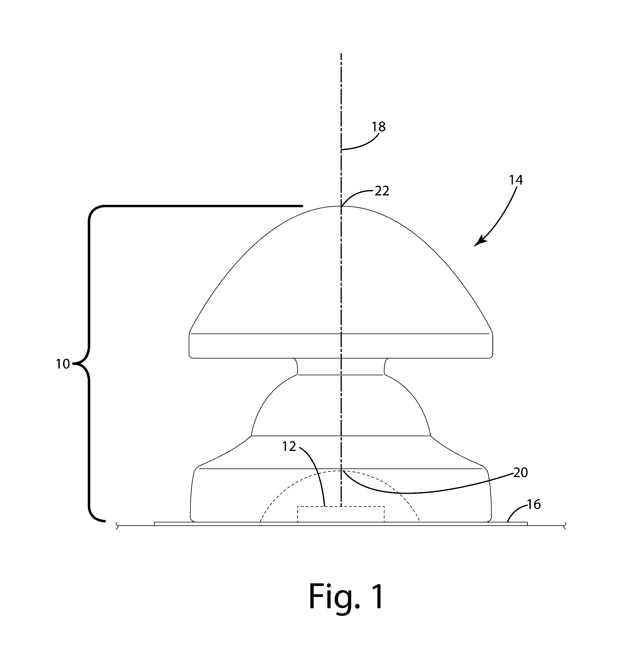
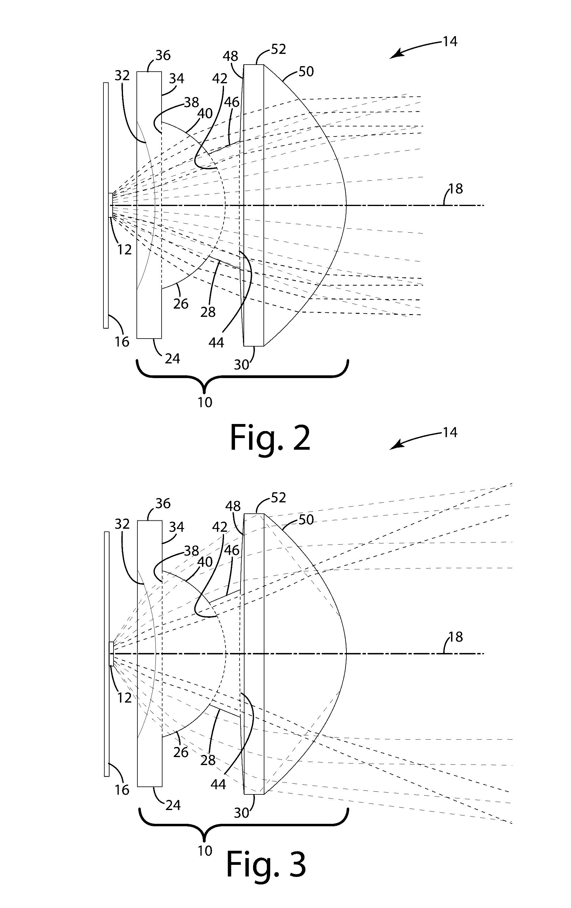
[0025]A compound lens in accordance with one embodiment is depicted in FIG. 1 and generally designated 10. The compound lens 10 is illustrated in combination with an LED 12 to form an optical emitter 14. The LED 12 is directly or indirectly mounted to a substrate 16, for example a pr...


PUM

PropertyMeasurementUnit
Electric potential / voltageaaaaaaaaaa
Lightaaaaaaaaaa
Optical propertiesaaaaaaaaaa

Abstract

A compound lens and a related method of manufacture are provided. The compound lens includes a first lens element and a second lens element such that a light emitting surface of the first lens element is integrally joined to a light receiving surface of the second lens element, the first and second lens element being in optical alignment with each other. The first and second lens element are molded from optical grade silicone and can achieve complex illumination objectives not possible with single lens constructions. The method of manufacture includes injecting a silicone resin molding compound into a mold cavity having the desired shape of the compound lens. The method of manufacture can include over-molding a lens holding member onto the compound lens and adding electro-optically active particles to a surface of the compound lens or to the silicone resin forming the compound lens.

Description

CROSS-REFERENCE TO RELATED APPLICATIONS[0001]This application claims the benefit of U.S. Application No. 62 / 147,186, filed Apr. 14, 2015, the disclosure of which is incorporated by reference in its entirety.FIELD OF THE INVENTION[0002]The present invention relates to compound lenses for use with light emitting diodes (LEDs) and other illumination sources.BACKGROUND OF THE INVENTION[0003]LEDs are semiconductor devices that emit light when a voltage is applied. LEDs continue to experience an increase in market share over conventional forms of lighting and benefit from a superior lighting quality and a high energy efficiency. In many instances, LEDs are less expensive to manufacture than conventional forms of lighting, including fluorescent and incandescent lighting for example.[0004]Existing LED systems often employ a compound lens to achieve shaping and control of emitted LED light in ways not available from single-element lenses. For example, it is known to use two or more individua...

Claims


Application Information

Patent Timeline
IPC IPC(8): F21V5/00B29D11/00B29C45/26B29C45/14F21V14/00B29C45/00
CPCF21V5/008B29K2105/16B29C45/0001B29C45/0013B29C45/0053B29C45/26B29C45/14778B29D11/00403B29D11/00865F21Y2101/02B29C2045/0079B29C2045/2683B29K2083/00B29K2105/253B29K2105/251F21V14/003B29C45/16
Inventor BRUNT, JR., HAROLD W.STRONG, MICHAEL R.PINTER, GILBERT M.
Owner VENTURA MFG1 LLC
Why Eureka
Try Eureka