

Modular Electric VTOL Aircraft
- Summary
- Abstract
- Description
- Claims
- Application Information
AI Technical Summary
Benefits of technology
Problems solved by technology
Method used
Image

Examples
first preferred embodiment
[0042]A preferred embodiment of the present invention will now be described.
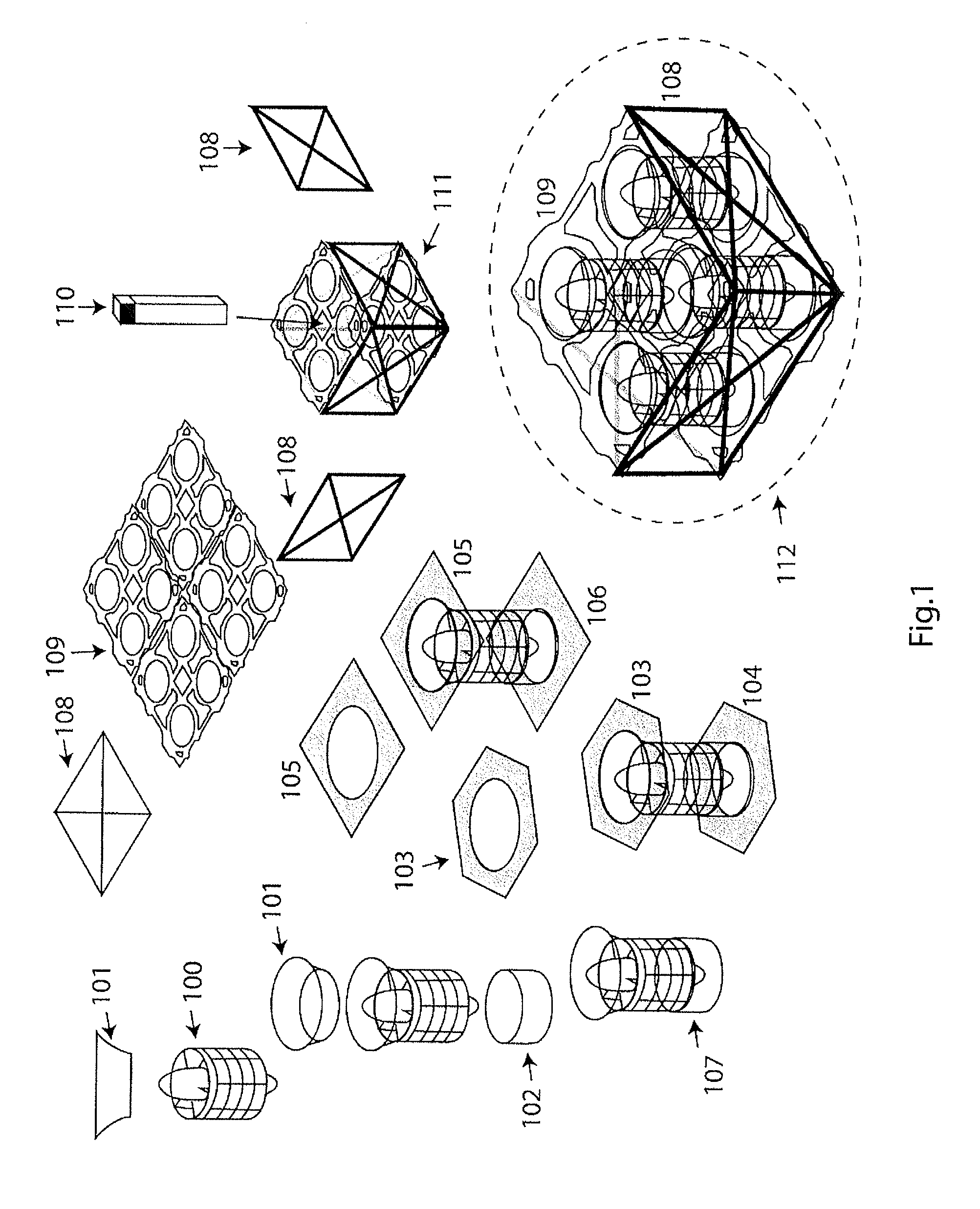
[0043]FIG. 1 shows a lifting module according to a preferred embodiment of the present invention. The preferred module is based around four electric ducted fans 100 which each preferably comprise two counter-rotating multi-bladed propellers driven by two brushless DC motors.
[0044]Inlets 101 and outlets 102,107 ensure optimal air intake and output giving an optimal thrust to electrical power ratio. Further adaptors 103,104 or 105,106 are preferably used for integrating seamlessly the electric ducted fan units into the module unit 112.
[0045]The module is preferably made from strong lightweight two-dimensional components 108,109 and preferably comprises a central heat sink block 110.
[0046]The completed module 112 preferably contains sufficient free space within the outer confining frame and outside the electric ducted fans for a lithium polymer (or other battery system and electronics to be mounted (not shown)....
second preferred embodiment
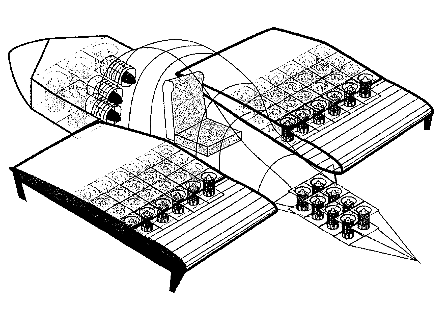
[0090]FIG. 5 shows three modules 501,502,503 used to produce a wing surface using front (505) and rear (506) profile modules. One or more electric ducted fans 504 can be used to produce lateral thrust. The variant 507 shows a wing composed of modules having a different geometric form.
[0091]FIG. 5 shows a second embodiment of the invention. Three modules are stacked together 501, 502, 503 and combined with shape modules 505,506 to produce a wing shape. 507 shows a variant where differently shaped modules are employed. The concept is designed to be integrated with the preferred embodiment. By including two such wing modules on either side of the aerial crane, and by using lateral fans 504 for lateral propulsion the aerial crane may be made to travel at up to 70 km / hr in a lateral direction. At these speeds the aerodynamic lifting force from the wing is considerable and hence the range of the aerial crane and its flight autonomy are greatly extended. Vanes may also be used to close the...
PUM
 Abstract
Description
Claims
Application Information