Rectifier and limiter circuit having a plurality of time constants and passive radio frequency tag

a limiter circuit and time constant technology, applied in the field of radio frequency identification, can solve the problems of inability to communicate, no longer function of rfid tag, permanent damage to the resistor, etc., and achieve the effect of increasing the read-write distance of the tag and avoiding saturation of reception at the card reader sid

Active Publication Date: 2016-10-27
EXCELIO TECH SHENZHEN +1
View PDF0 Cites 2 Cited by
  • Summary
  • Abstract
  • Description
  • Claims
  • Application Information

AI Technical Summary

Benefits of technology

[0009]A technical problem to be solved by embodiments of the present invention is to provide a rectifier and limiter circuit having a plurality of time constants and a passive radio frequency tag, where controlling the circuit voltage is realized by adjusting the discharge paths of the passive radio frequency tag, the saturation of reception at the card reader side is avoided, and the read-write distance of the tag is effectively increased.

Problems solved by technology

As a result, the transistor is damaged permanently, and the RFID tag no longer functions.
When the passive RFID tag is too close to the card reader or the electromagnetic energy sent from the card reader is too high, a load modulation signal coupled from the RFID tag side is likely to result in saturation of the receiving end of the card reader, thus to fail the communication.
Such failure is more likely to occur in an RTF (Reader Talk First) communication mode where the card reader sends a command first and then waits for a response from the RFID tag.
If the energy is too low, the tag can not demodulate the command well and execute the uplink communication, that is, the card reader can not read data in the tag.

Method used


Image

  • Rectifier and limiter circuit having a plurality of time constants and passive radio frequency tag
  • Rectifier and limiter circuit having a plurality of time constants and passive radio frequency tag
  • Rectifier and limiter circuit having a plurality of time constants and passive radio frequency tag

Examples


embodiment 1

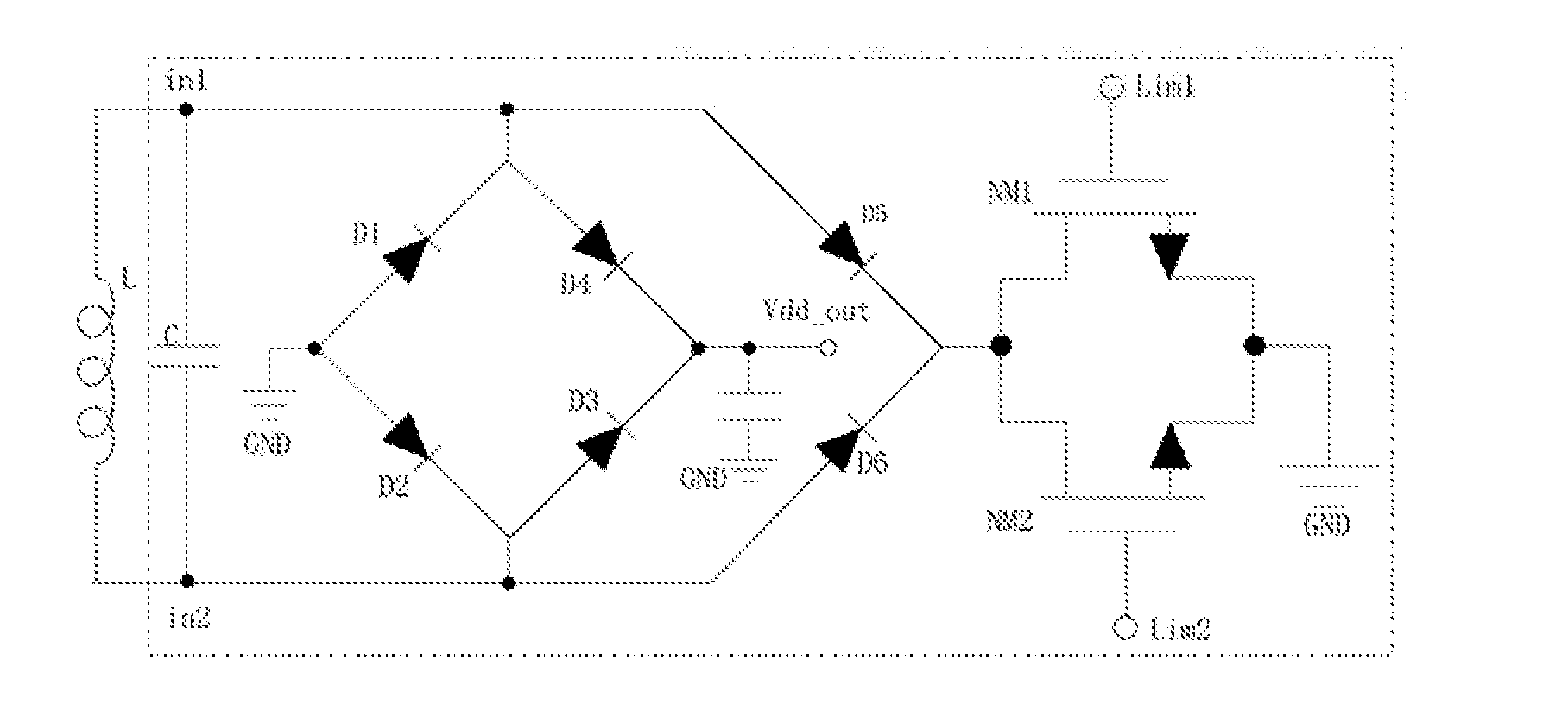
[0035]FIG. 1 is a general structure diagram of Embodiment 1 of a circuit according to the present invention. A rectifier and limiter circuit having a plurality of time constants described in the present invention includes:

[0036]a resonant capacitor C, which is connected, between a first antenna terminal in1 and a second antenna terminal in2, in parallel to a resonant inductor L, and configured to form a resonant circuit together with the resonant inductor L, receive an external electromagnetic field and couple the external electromagnetic field to a rectifier circuit;

[0037]a rectifier circuit, the input terminal of which is connected to the first antenna terminal in1 and the second antenna terminal in2 and configured to convert AC power, to which the resonant circuit is coupled, into DC power and output the DC power to an external load circuit, and meanwhile, one output terminal of which is grounded by two discharge paths connected in parallel and configured to output charge to the ...

second embodiment

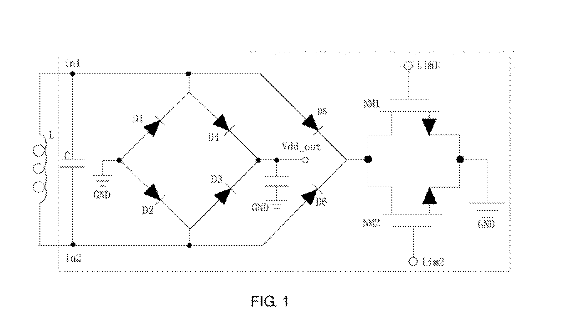
[0043]The structure of the second rectifier branch is as shown in FIG. 2. In this embodiment, the second rectifier branch is a fifth diode D5 and a sixth diode D6 connected between the first antenna terminal in1 and the second antenna terminal in2, as well as a seventh diode D7 and an eighth diode D8. The cathode terminals of the fifth diode D5 and the sixth diode D6 are connected to each other and to the input terminal of the first discharge path, and the cathode terminals of the seventh diode D7 and the eighth diode D8 are connected to each other and to the input terminal of the second discharge path.

[0044]With respect to the structure of the first embodiment as shown in FIG. 1, the structure of the second embodiment of the second rectifier branch as shown in FIG. 2 improves the flexibility of further controlling the amplitude limitation and current discharge. Corresponding to the leakage discharge circuits controlled by the control signals having different time constants, the siz...

third embodiment

[0045]The structure of the second rectifier branch is as shown in FIG. 3. The second rectifier branch is a third N-type MOS transistor NM3 and a fourth N-type MOS transistor NM4 connected between the first antenna terminal in1 and the second antenna terminal in2. The gate and drain of the third N-type MOS transistor NM3 are respectively connected to the first antenna terminal, the gate and drain of the fourth N-type MOS transistor NM4 are respectively connected to the second antenna terminal, and the source of the third N-type MOS transistor NM3 are connected to the source of the fourth N-type MOS transistor NM4 and to the input terminals of the two discharge paths.


PUM


Abstract

The present invention relates to the technical field of radio frequency identification, in particular to a rectifier and limiter circuit having a plurality of time constants and a passive radio frequency tag containing this rectifier and limiter circuit. By applying analog control signals with different time constants to control terminals of two discharge paths of the rectifier and limiter circuit, respectively, i.e., adjusting the voltage amplitude at different switching speeds, switching the two discharge paths from a completely open state to a completely closed state is realized. Discharging is performed properly according to the amount of charge at antenna terminals and the level of energy of the tag, thus to improve the demodulation capacity of the tag and increase the read-write distance of the tag.

Description

CROSS-REFERENCE TO RELATED APPLICATIONS[0001]This application is a continuation of International Patent Application No. PCT / CN2015 / 070145 with a filing date of Jan. 6, 2015, designating the United States, now pending, and further claims priority to Chinese Patent Application No. 201410009326.0 with a filing date of Jan. 8, 2014. The content of the aforementioned applications, including any intervening amendments thereto, are incorporated herein by reference.TECHNICAL FIELD[0002]The present invention belongs to the technical field of radio frequency identification, and particularly relates to a rectifier and limiter circuit having a plurality of time constants and a passive radio frequency tag containing this rectifier and limiter circuit.BACKGROUND OF THE PRESENT INVENTION[0003]Passive radio frequency identification (RFID) tags, as they themselves are not designed with any battery, operate relying on electromagnetic energy sent from a card reader. Due to their simple structure and e...

Claims


Application Information

Patent Timeline
Patent Type & Authority Applications(United States)
IPC IPC(8): H02M7/04H02M1/32G06K7/10
CPCH02M7/04H02M1/32G06K7/10009G06K19/0723H02M7/062G06K19/0715H02J50/12H02M7/043H02M1/322
Inventor WU, PATRICK,BIANHAN, FUQIANG
Owner EXCELIO TECH SHENZHEN
Why Eureka
Try Eureka