Systems & methods for ocular anterior segment tracking, alignment, and dewarping using optical coherence tomography

a technology of optical coherence tomography and system, applied in the field of methods and systems in optical coherence tomography, can solve problems such as data interpretation or processing, patient using optical coherence tomography presents different problems, and restricted depth and breadth of imaging, so as to achieve accurate dewarping and improve accuracy.

Active Publication Date: 2016-11-03
CARL ZEISS MEDITEC INC
View PDF3 Cites 9 Cited by
  • Summary
  • Abstract
  • Description
  • Claims
  • Application Information

AI Technical Summary

Benefits of technology

[0015]The systems and methods disclosed herein are aimed to control accurate positioning of the structures found in the anterior segment of an eye of a patient; to improve the ability to dewarp corneal surfaces; and, to provide full-range OCT imaging capability. The positioning control includes appropriate placement of the corneal surfaces within the OCT image as well as maintaining that position during examination (i.e., tracking). One aspect of the accurate positing of the anterior segment is to control the position of the delay which will allow good anterior segment positioning. A method is disclosed which permits fast alignment of the position of the delay and another aspect is presented to track on anatomical structures found within the anterior segment. The embodiments can be used alone or in combination to improve the overall accuracy of measurements made on anterior segment OCT images.
[0016]The ultimate goal of anterior segment imaging is to detect and measure specific features in the anterior chamber of the eye, such as corneal surfaces, iris, crystalline lens, and various structural and functional features such as scleral spur, iridocorneal angle, Schlemm's canal, Schwalbe's line, as well as the trabecular meshwork. Controlled anterior segment positioning allows the optimal placement of corneal surfaces to permit more accurate dewarping, a vital prerequisite to obtaining accurate geometric metrics from the imaging data.
[0020]The combination of precise tracking and optimum placement of corneal surfaces allows accurate automated dewarping to be accomplished. In various embodiments, systems and methods are also presented to achieve more accurate dewarping in the situation where there is limited field-of-view anterior segment imaging, in which there is incomplete detection of one or both of the corneal surfaces. This limitation is overcome by determining more complete information regarding the profiles of these surfaces. More complete information can yield improved accuracy dewarping, which is an important step in realistic geometric measurements of anterior segment structures. The systems and methods presented herein can be fully automated or configured to report the results to a user, who then can implement any suggested adjustments.

Problems solved by technology

Elements of all three of these components can lead to artifacts that can cause problems in data interpretation or processing.
Imaging of the anterior segment of an eye of a patient using OCT systems presents different problems than encountered with the more commonly performed OCT imaging of the retina.
Problems encountered with OCT anterior segment imaging include distortions of the acquired image from a true geometric image, the restricted nature of the depth and breadth of imaging, and the difficulty in obtaining good real-time positional control during image acquisition.
Beam geometry distortions arise due to the non-telecentric scanning of the OCT beam used to obtain a 2D image (a B-scan) and also due to the optical path length, which is related to scan sag, changing the curvature of the cornea.
This results in a distorted image and thus any measurements made of structures in an undewarped image, can result in erroneous values.
Other distortions are caused by light rays encountering interfaces between media of different indices of refraction.
In some cases, the mirror image is distorted due to dispersion mismatch in the two arms of the interferometer, causing it to appear blurred.
view. When imaging the anterior segment of the eye, visualization of multiple structures that extend throughout the entire axial field-of-view of the image is desirable, so limiting the reported field-of-view to half of the acquired data is not an optimal sol
Hardware-based approaches, unfortunately, add cost and complexity to the system, and several approaches have technical limitations.
The majority of these methods require multiple frame acquisitions and heavy post-processing, which obviates real-time display, visualization, and correction.
Should the patient move longitudinally, as discussed above, then the complex conjugate and real images could overlap, causing segmentation problems, hence deficiencies in the information provided to the dewarping process.
However, these reference marks are not available in OCT anterior segment imaging.
The depth of imaging in the anterior segment poses a severe problem, as the distance between the anterior surfaces of cornea and crystalline lens is 3.5 mm.
Thus simultaneous imaging of a large portion of the anterior segment is currently not possible.

Method used


Image

  • Systems & methods for ocular anterior segment tracking, alignment, and dewarping using optical coherence tomography
  • Systems & methods for ocular anterior segment tracking, alignment, and dewarping using optical coherence tomography
  • Systems & methods for ocular anterior segment tracking, alignment, and dewarping using optical coherence tomography

Examples


Embodiment Construction

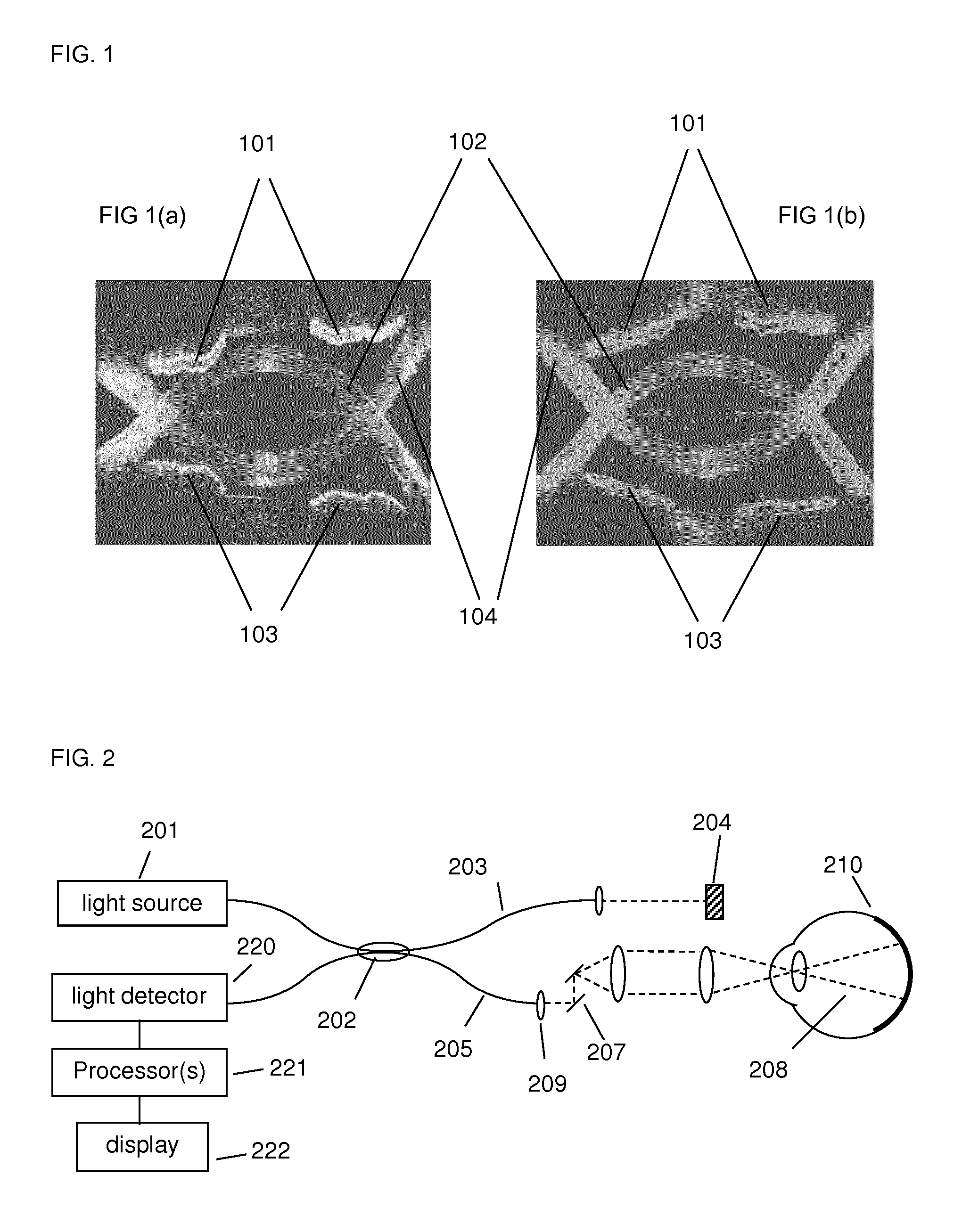
[0055]A generalized Fourier Domain optical coherence tomography (FD-OCT) system used to collect an OCT dataset suitable for use with the present set of embodiments is illustrated in FIG. 2. An FD-OCT system includes a light source, 201, typical sources including, but not limited to, broadband light sources with short temporal coherence lengths or swept laser sources. Light from source (201) is routed, typically by optical fiber (205), to illuminate the sample (210), which could be any of the tissues or structures with an eye. The light is scanned, typically with a scanner (207) between the output of the fiber and the sample, so that the beam of light (dashed line 208) is scanned over the area or volume to be imaged. Light scattered from the sample is collected, typically into the same fiber (205) used to route the light for illumination. Reference light derived from the same source (201) travels a separate path, in this case involving fiber (203) and retro-reflector (204). Those ski...


PUM


Abstract

The present application discloses methods and systems to track the anterior segment while establishing a position of the delay which will permit good control of the placement of anterior segment structures. This allows accurate dewarping by maximizing the amount of corneal surface that is imaged as well as reducing or eliminating overlap between real and complex conjugate images present in frequency-domain optical coherence tomography. A method to dewarp surfaces given partial corneal surface information is also disclosed.

Description

[0001]This application claims priority from provisional applications U.S. Ser. No. 61 / 918,107 filed 19 Dec. 2013 and U.S. Ser. No. 62 / 064,932 filed 10 Oct. 2014.TECHNICAL FIELD[0002]The present application discloses methods and systems in optical coherence tomography to improve the quality of anterior segment imaging in the eye of a patient.BACKGROUND[0003]Optical coherence tomography (OCT) is an optical imaging technology for imaging non-invasively biological tissues. The basis of the technique is low-coherence interference between a reference beam and light reflected from structural surfaces such as tissues. Depending on the scanning or imaging configuration, various dimensions can be probed such as a line (called an A-scan), transverse scanning can produce a 2D surface known as a B-scan, and with multiple adjacent surfaces a 3D volume can be obtained.[0004]In frequency-domain OCT (FD-OCT), the optical path length difference between the sample and reference arm is not mechanically...

Claims


Application Information

Patent Timeline
Patent Type & Authority Applications(United States)
IPC IPC(8): A61B3/00A61B3/117A61B3/107G06K9/00G06T7/00G06K9/52G06T7/60A61B3/10G06T5/00
CPCA61B3/0025A61B3/102A61B3/117A61B3/107G06T5/006G06T7/0012G06T2207/30196G06K9/52G06T7/60G06K9/0061G06K9/00617G06T2207/30041G06T2207/10072G06T7/004G06T3/0093G06T2207/10101G06T7/70G06V40/193G06V40/197
Inventor BAGHERINIA, HOMAYOUN
Owner CARL ZEISS MEDITEC INC
Why Eureka
Try Eureka