Automatic ultrasound beam steering and needle artifact suppression

a technology of automatic ultrasound and ultrasound beam, applied in the field of segmenting medical instruments in ultrasound images, can solve the problems of affecting the clinical value of needle detection, affecting and exacerbate the difficulty in visualizing, so as to enhance the appearance of specular reflectors and enhance detection

Inactive Publication Date: 2016-11-03
KONINKLJIJKE PHILIPS NV
View PDF4 Cites 13 Cited by
  • Summary
  • Abstract
  • Description
  • Claims
  • Application Information

AI Technical Summary

Benefits of technology

[0021]In sub-aspects or related aspects, US beam steering is employed to enhance the appearance of specular reflectors in the image. Next, a pixel-wise needle classifier trained from previously acquired ground truth data is applied to segment the needle from the tissue background. Finally, a Radon or Hough transform is used to detect the needle pose. The segmenting is accomplished via statistical boosting of wavelet features. The whole process of acquiring an image, segmenting the needle, and displaying an image with a visually enhanced and artifact-free needle-only overlay is done automatically and without the need for user intervention.
[0022]Validation results using ex-vivo and clinical datasets show enhanced detection in challenging ex-vivo and clinical datasets where sub-optimal needle position and tissue artifacts cause intensity based segmentation to fail.

Problems solved by technology

In addition to above-noted visualization difficulties, visualization is problematic when the needle is not yet deeply inserted into the tissue.
The Cheung difficulty in distinguishing the needle from “needle-like” specular deflector is exacerbated in detecting a small portion of the needle, as when the needle insertion is just entering the field of view.
Yet, the clinical value of needle detection is questionable if, to determine the needle's pose, there is a need to wait until the needle is more deeply inserted.

Method used


Image

  • Automatic ultrasound beam steering and needle artifact suppression
  • Automatic ultrasound beam steering and needle artifact suppression
  • Automatic ultrasound beam steering and needle artifact suppression

Examples


Embodiment Construction

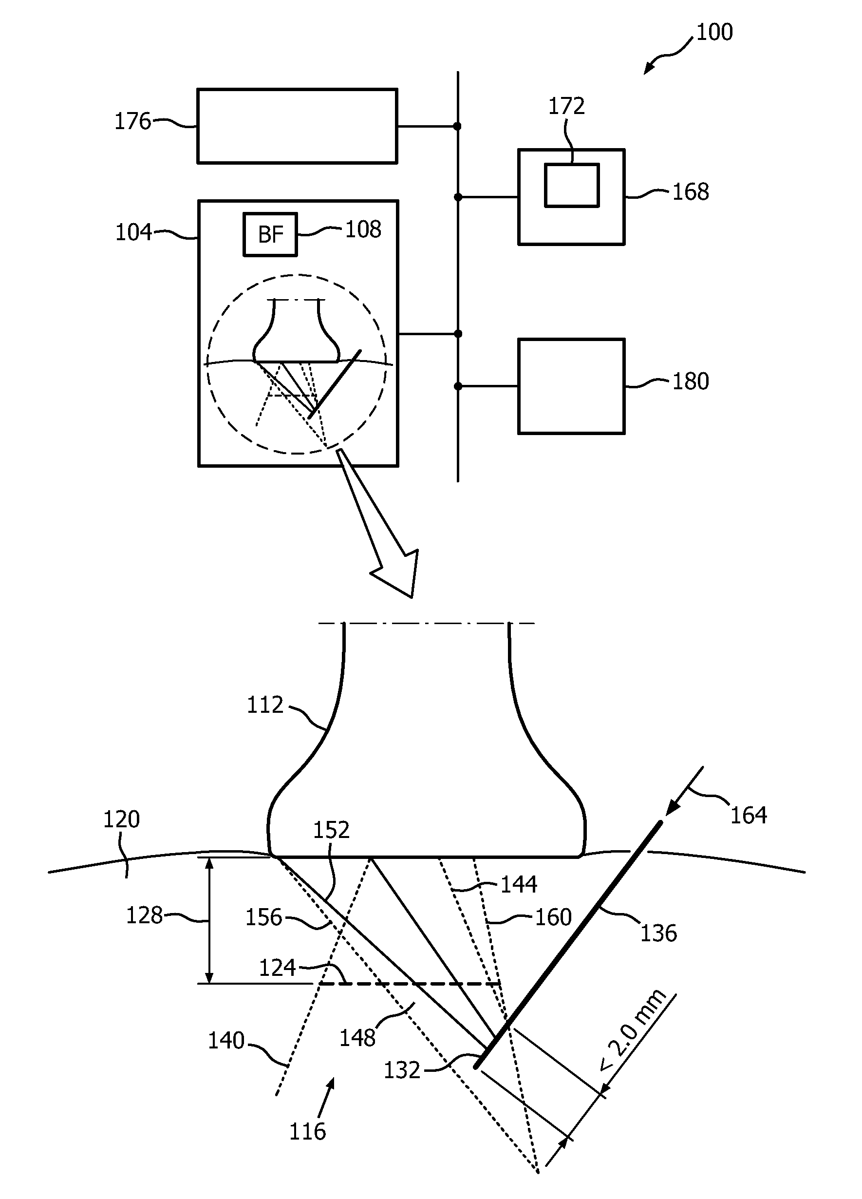
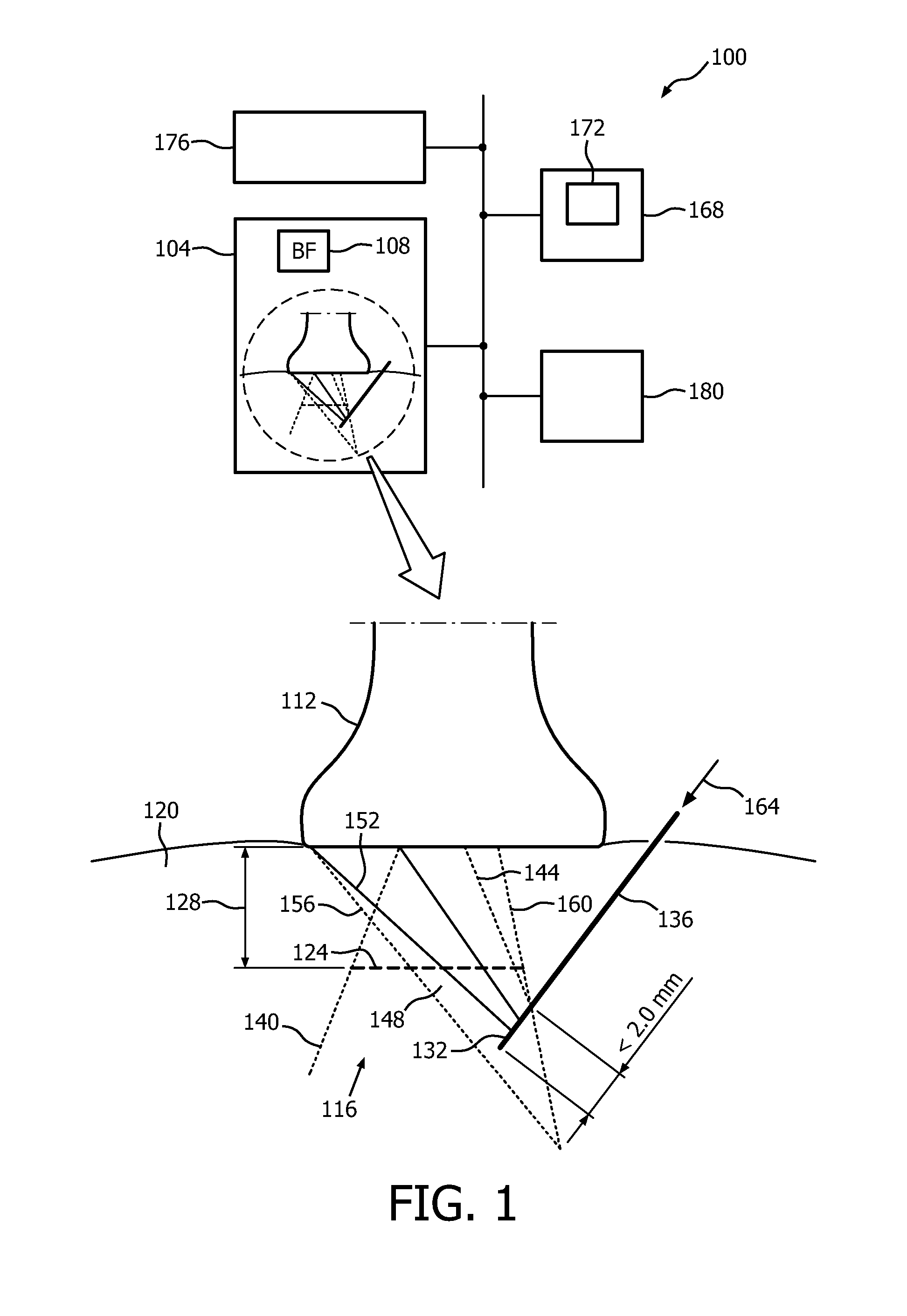
[0029]FIG. 1 depicts, by way of illustrative and non-limitative example, a real time classification-based medical image segmentation apparatus 100. It includes an ultrasound image acquisition device 104, such as a scanner. The device 104 includes a beamformer 108 and an ultrasound imaging probe 112. The probe 112 may be a linear array probe. It can be set with a field of view 116, in body tissue 120, that is defined by a lateral span 124 at any given imaging depth 128. The apparatus 110 can use the probe 112 to detect, in real time, entry of at least a portion 132 of a medical needle 136 into the field of view 116. The field of view 116 is defined by two boundary lines 140, 144. Detection of the needle 136 can occur with as little as 2.0 millimeters of the needle 136 being inserted into the field of view 116. This allows for earlier detection of the needle than available from existing methodologies. To improve the image of the needle 136, the current field of view 116 may change to ...


PUM


Abstract

A classification-based medical image segmentation apparatus includes an ultrasound image acquisition device configured for acquiring, from ultrasound, an image depicting a medical instrument such as needle; and machine-learning-based-classification circuitry configured for using machine-learning-based-classification to, dynamically responsive to the acquiring, segment the instrument by operating on information (212) derived from the image. The segmenting can be accomplished via statistical boosting (220) of parameters of wavelet features. Each pixel (216) of the image is identified as “needle” or “background.” The whole process of acquiring an image, segmenting the needle, and displaying an image with a visually enhanced and artifact-free needle-only overlay may be performed automatically and without the need for user intervention.

Description

CROSS REFERENCE TO PRIOR APPLICATION[0001]This application claims the benefit of U.S. Provisional Patent Application No. 61 / 918,912, filed on Dec. 20, 2013 which is hereby incorporated by reference herein.FIELD OF THE INVENTION[0002]The present invention relates to segmenting a medical instrument in an ultrasound image and, more particularly, to dynamically performing the segmentation responsive to acquiring the image. Performing “dynamically” or in “real time” is interpreted in this patent application as completing the data processing task without intentional delay, given the processing limitations of the system and the time required to accurately measure the data needed for completing the task.BACKGROUND OF THE INVENTION[0003]Ultrasound (US) image guidance increases the safety and efficiency of needle guided procedures by enabling real-time visualization of needle position within the anatomical context. The ability to use ultrasound methods like electronic beam steering to enhance...

Claims


Application Information

Patent Timeline
Patent Type & Authority Applications(United States)
IPC IPC(8): A61B8/08G06K9/66G06K9/62A61B8/00G06T7/00G06V10/143
CPCA61B8/0841A61B8/461A61B8/5215A61B8/5269G06T2207/10132G06T7/004G06T7/0081G06K9/6267G06K9/66G06T7/0012G06T2207/30021G06T7/70G06T7/11G06T7/143G06V10/143G06V10/446G06V10/7747G06F18/24G06F18/2148
Inventor PARTHASARATHY, VIJAYNG, GARY CHENG-HOWHATT, CHARLES RAY
Owner KONINKLJIJKE PHILIPS NV
Why Eureka
Try Eureka