Spinal fusion surgery instrument for implanting and intervertebral cage thereof

Inactive Publication Date: 2016-11-03
INTAI TECH CORP
View PDF10 Cites 40 Cited by
  • Summary
  • Abstract
  • Description
  • Claims
  • Application Information

AI Technical Summary

Benefits of technology

[0010]In view of the aforementioned problem, a primary objective of the present invention provides a spinal fusion surgery instrument for implanting and an intervertebral cage thereof which change an angle with respect to the location of

Problems solved by technology

When the intervertebral disk is damaged severely, two adjacent spine bones may approach with each other abnormally to suppress the surrounding nerves and the pain caused by the nerve compression may disable the patient from exercising.
When the implant instrument and the intervertebral cage are implanted into the human body, the surgeon can only operate the surgical instruments according the instinct, touch and experience as it is difficult to do through visual contact.
Moreover, conventional endoscope and surgery instrument for mini-invasive surgery are separate devices, so the operative field is easily shielded

Method used


Image

  • Spinal fusion surgery instrument for implanting and intervertebral cage thereof
  • Spinal fusion surgery instrument for implanting and intervertebral cage thereof
  • Spinal fusion surgery instrument for implanting and intervertebral cage thereof

Examples


first embodiment

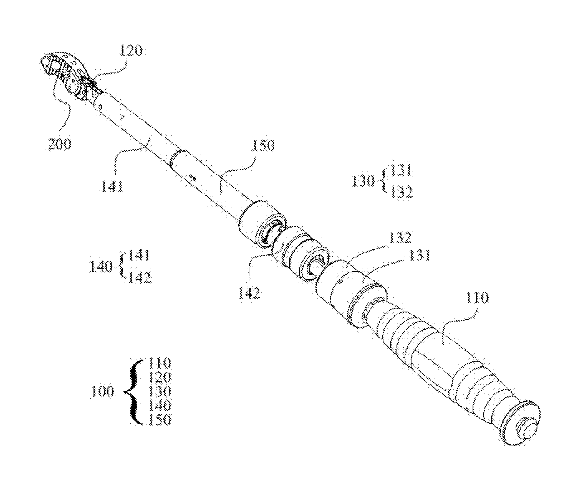
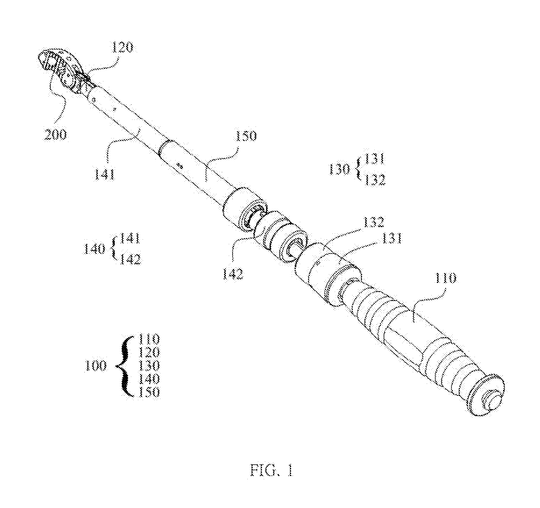
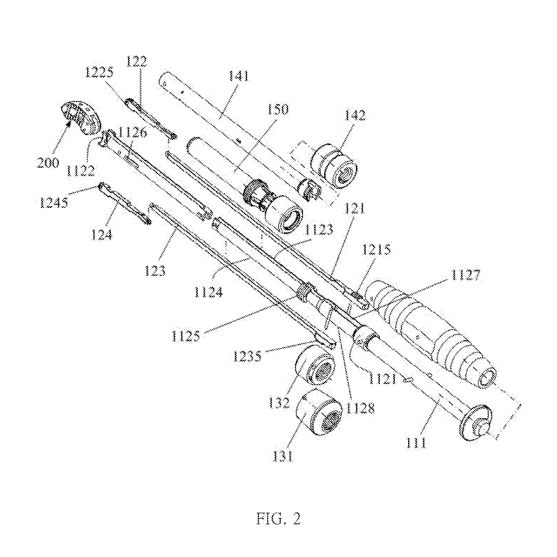
[0040]Please refer to FIG. 1, FIG. 2, and FIG. 3 which respectively show a spinal fusion surgery instrument for implanting and an intervertebral cage thereof of the present invention. As shown in the FIGS., an implant instrument 100, which may be a spinal fusion surgery instrument for implanting, of the present invention is applied to grip and implant an intervertebral cage 200 to a location between two adjacent spine bones. The intervertebral cage 200 has a guiding end 211 and a gripping end 212. The implant instrument 100 includes a body 110, a gripper subassembly 120, a first control subassembly 130, a second control subassembly 140 and a measuring unit 150. The measuring unit 150 is sheathed outside the sleeve 141 of the second control subassembly 140. The body 110 includes a grasp rod 111 and a fixed rod 112. The gripper subassembly 120 includes a first connecting member 121, a first gripping member 122, a second connecting member 123 and a second gripping member 124. The first...


PUM


Abstract

A spinal fusion surgery instrument for implanting and an intervertebral cage thereof are provided. The spinal fusion surgery instrument includes a body, a gripper subassembly, a first control subassembly, and a second control subassembly. The first control subassembly is provided to generate a displacement between a first connecting member and a second connecting member of the gripper subassembly to change the angle of gripper of the intervertebral cage. The second control subassembly is provided to enable a first gripping member and a second gripping member of the gripper subassembly separating smoothly from the dowel pins of the intervertebral cage. By means of the operation model, the spinal fusion surgery instrument may be controlled easily, and the orientation of the intervertebral cage may be promoted in the process of the surgery.

Description

CROSS-REFERENCE TO RELATED APPLICATION[0001]This application is a continuation-in-part of U.S. patent application Ser. No. 14 / 828,266, filed Aug. 17, 2015, which claims benefit of Taiwan Patent Application No. 104113539, filed Apr. 28, 2015, the disclosures of which are incorporated herein its entirety by reference.BACKGROUND OF THE INVENTION[0002]1. Field of the Invention[0003]The present invention generally relates to an implant instrument and an intervertebral cage thereof, in particular to the implant instrument and the intervertebral cage thereof which are feasible to be applied to the transforaminal lumbar interbody fusion (TLIF).[0004]2. Description of the Related Art[0005]Generally, the vertebrae disease is caused by long-term inappropriate pose, sport injury or comes with ages. When the intervertebral disk is damaged severely, two adjacent spine bones may approach with each other abnormally to suppress the surrounding nerves and the pain caused by the nerve compression may ...

Claims


Application Information

Patent Timeline
IPC IPC(8): A61F2/46
CPCA61F2002/4629A61F2/4611A61F2/4455A61F2/4657A61F2002/30112A61F2002/30471A61F2002/30538A61F2002/30784A61F2002/4627A61F2002/4662A61F2002/4696
Inventor CHO, MING-CHENGLIN, DIAN-YINGTSAI, YUNG-FANGCHUANG, SHIN-CHANGCHEN, HUNG-YI
Owner INTAI TECH CORP
Why Eureka
Try Eureka