Supercharge Your Innovation With Domain-Expert AI Agents!

Magnetoresistive effect oscillator

a technology of magnetoresistive effect and oscillator, which is applied in the direction of oscillator, magnetic body, electrical apparatus, etc., can solve the problems of inability to perform high-speed magnetic recording, inability to apply magnetoresistive effect elements to high-speed communications, and inability to achieve high-speed magnetic recording, the effect of reducing the energy of the pulse curren

Active Publication Date: 2016-11-03
TDK CORPARATION
View PDF1 Cites 4 Cited by
  • Summary
  • Abstract
  • Description
  • Claims
  • Application Information

AI Technical Summary

Benefits of technology

The present invention aims to provide a magnetoresistive effect oscillator that can make the oscillation rise faster in the magnetoresistive effect element.

Problems solved by technology

However, the above proposed operation method has a problem that the oscillation caused in the magnetoresistive effect element takes a time to rise.
If the oscillation caused in the magnetoresistive effect element takes a time to rise, a problem arises in that the magnetoresistive effect element cannot be applied to high-speed communications, for example.
However, another problem arises in that the magnetic recording cannot be performed at a high speed, if the oscillation caused in the magnetoresistive effect element takes a time to rise.

Method used


Image

  • Magnetoresistive effect oscillator
  • Magnetoresistive effect oscillator
  • Magnetoresistive effect oscillator

Examples


first embodiment

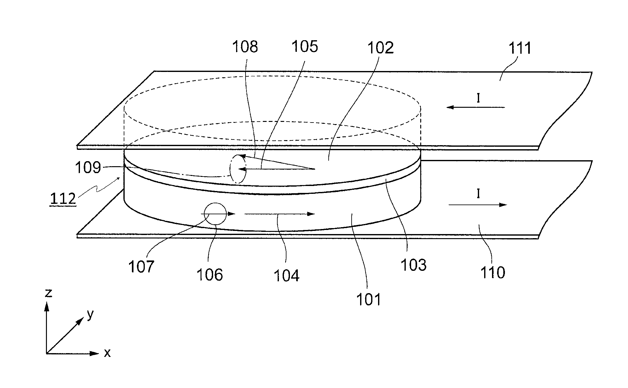
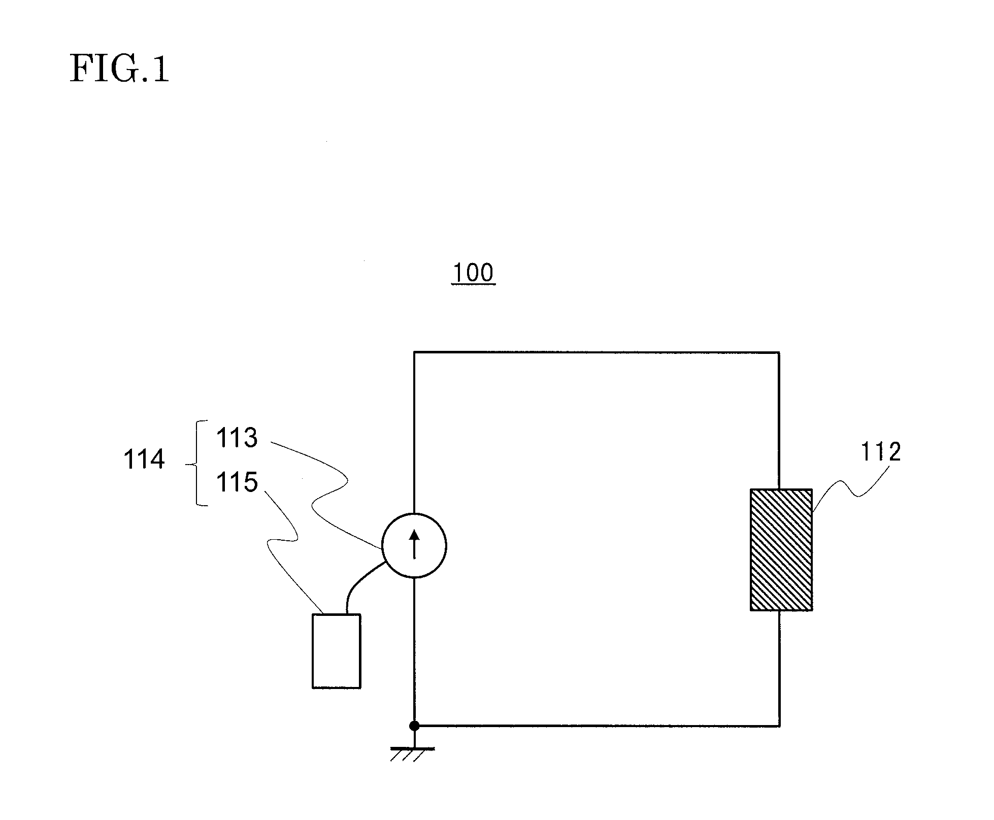
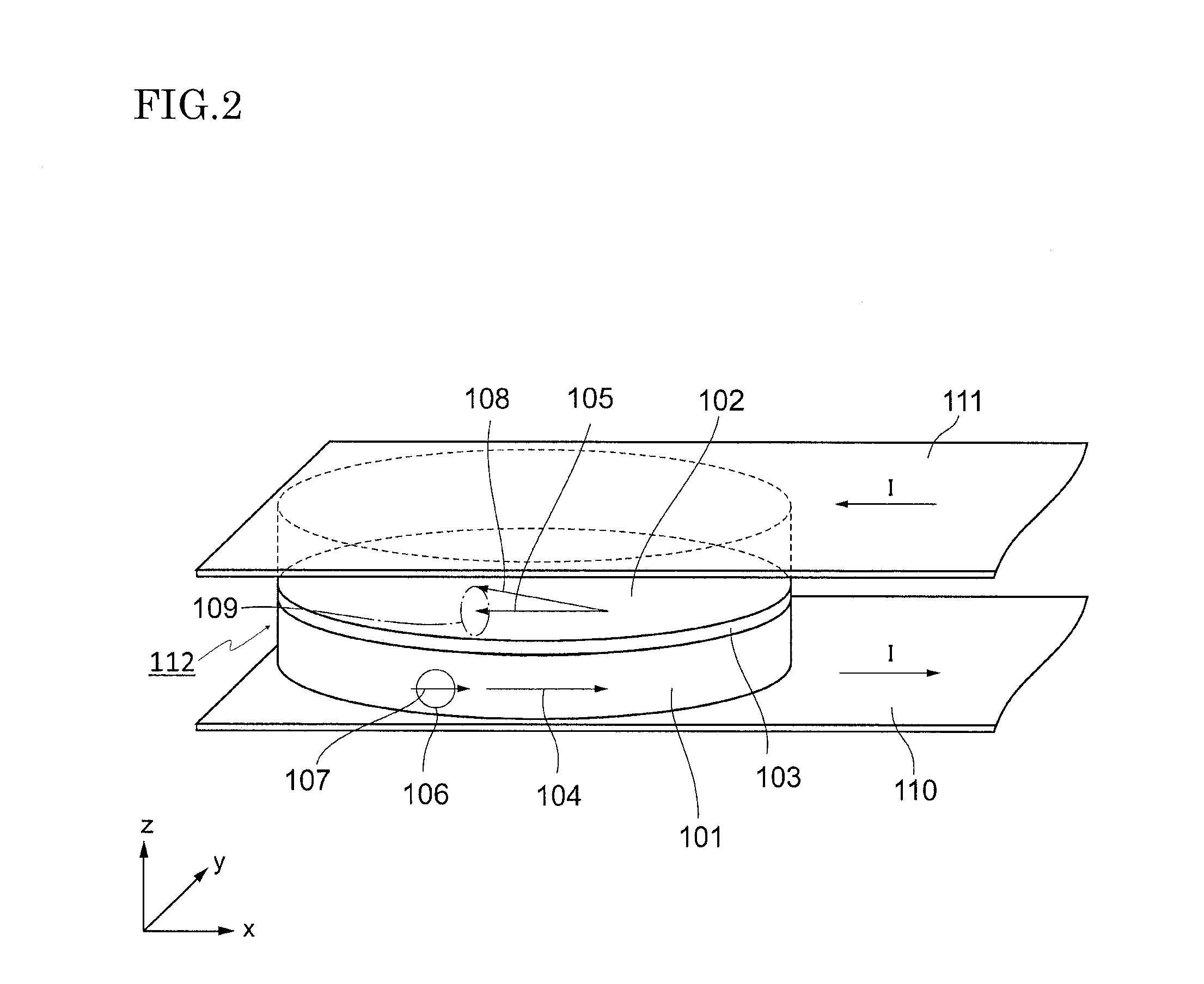
[0062]FIG. 1 is a circuit diagram of a magnetoresistive effect oscillator 100. The magnetoresistive effect oscillator 100 includes a magnetoresistive effect element 112 and a current applying unit 114 for applying a current to the magnetoresistive effect element 112. The current applying unit 114 includes a current source 113 and a control unit 115. The current source 113 is connected to be able to supply the current to the magnetoresistive effect element 112. The control unit 115 controls the operation of the current source 113. FIG. 2 illustrates an example of configuration of the magnetoresistive effect element 112. The magnetoresistive effect element 112 includes a first magnetic layer 101, a second magnetic layer 102, and a spacer layer 103 arranged between them. The first magnetic layer 101 is electrically connected to a first electrode 110, and the second magnetic layer 102 is electrically connected a second electrode 111, respectively. The current source 113 is connected to ...

second embodiment

[0100]FIG. 5 is a schematic view of a magnetoresistive effect element 112 according to a second embodiment. The second embodiment is similar to the first embodiment except for the magnetization direction of a second magnetic layer 102 before the application of the current to the magnetoresistive effect element 112, i.e., the direction of the effective magnetic field in the second magnetic layer 102, and for the direction of the current applied to the magnetoresistive effect element 112. The direction of the effective magnetic field in the second magnetic layer 102 is substantially the same as the magnetization direction of a first magnetic layer 101. Furthermore, a current I in the negative direction is applied to flow in a direction perpendicular to a film surface of the magnetoresistive effect element 112. When such a current is applied, a conduction electron 106 flows in a direction opposite to the direction of the current I, i.e., in a direction toward the first magnetic layer 1...

simulation example 1

[0104]For the magnetoresistive effect oscillator 100 of the first embodiment, a simulation was performed on the basis of the equation (9), and the rise time of the oscillation in the magnetoresistive effect element 112 was calculated. The second magnetic layer 102 had an elliptic shape with a major axis of 135×a minor axis of 65×a thickness of 2.5 nm3. It is here assumed that an x-axis direction is defined as the direction of the major axis, a y-axis direction is defined as the direction of the minor axis, and a z-axis direction is defined as the direction of the thickness. The material of the first magnetic layer 101 was FeCo, and the material of the second magnetic layer 102 was NisoFe20. The magnetization in the first magnetic layer 101 was fixed through exchange-coupling with respect to an antiferromagnetic material (not illustrated) that was positioned just under the first magnetic layer 101. The material of the spacer layer 103 was Cu, i.e., a nonmagnetic metal.

[0105]The secon...


PUM


Abstract

A magnetoresistive effect oscillator executes a first step of applying a current, which has a first current density larger than a critical current density JO for oscillation, to a magnetoresistive effect element for a time TP, and then executes a second step of applying a current, which has a second current density JS smaller than the first current density and not smaller than the critical current density JO for oscillation, to the magnetoresistive effect element. The following formulae (1), (2) and (3), or the following formulae (1) and (4) are satisfied on an assumption that an average value of the first current density during the time TP in the first step is JP, a critical current density for magnetization reversal of the magnetoresistive effect element is JR, and a magnetization reversal time of the magnetoresistive effect element is TR:0.1×TR(JR-JO)Jp-JS<Tp<0.9×TRJR-JOJS-JO(1)TP<TR(JR-JO)JP-JO(2)JR≤JP(3)JP<JR.(4)

Description

BACKGROUND OF THE INVENTION[0001]1. Field of the Invention[0002]The present invention relates to a magnetoresistive effect oscillator.[0003]2. Description of the Related Art[0004]A magnetoresistive effect oscillator is an oscillator utilizing precession of magnetization in a magnetic layer of a magnetoresistive effect element, the precession being generated upon application of a current to the magnetoresistive effect element. In such an oscillator, a resistance value of the magnetoresistive effect element is changed at a high frequency due to the precession of magnetization in the magnetic layer of the magnetoresistive effect element, thereby causing the magnetoresistive effect element to oscillate. In recent years, studies on the magnetoresistive effect oscillator have been conducted intensively. Japanese Unexamined Patent Application Publication (Translation of PCT Application) No. 2010-519760 discloses an operation method of operating a magnetoresistive effect oscillator at a low...

Claims


Application Information

Patent Timeline
IPC IPC(8): H03B15/00H01F10/26
CPCH01F10/26H03B15/006H01F10/324H01F10/3286H03B5/1206H03B15/00
Inventor SUZUKI, TSUYOSHISUZUKI, EIJI
Owner TDK CORPARATION
Features
  • R&D
  • Intellectual Property
  • Life Sciences
  • Materials
  • Tech Scout
  • Unparalleled Data Quality
  • Higher Quality Content
  • 60% Fewer Hallucinations
Learn More