RADIO FREQUENCY IDENTIFICATION (RFID) TAG(S) and SENSOR(S)

a radio frequency identification and sensor technology, applied in the field of sensing a detectable environmental condition, can solve the problems of loss of transmitted power, critical loss, and inability to solve the basic need

Active Publication Date: 2016-11-10
RFMICRON
View PDF3 Cites 27 Cited by
  • Summary
  • Abstract
  • Description
  • Claims
  • Application Information

AI Technical Summary

Benefits of technology

[0038]Yet another embodiment comprises multiple sensing engines that are located within a single integrated circuit (IC) or die that functions as a passive RFID tag. A generic sensing interface on the passive RFID tag provides add...

Problems solved by technology

The mismatch between fC and fR results in loss of transmitted power.
In some applications, this may not be of particular concern, but, in others, such as in RF identification (“RFID”) applications, such losses are of critical concern.
However, such struct...

Method used


Image

  • RADIO FREQUENCY IDENTIFICATION (RFID) TAG(S) and SENSOR(S)
  • RADIO FREQUENCY IDENTIFICATION (RFID) TAG(S) and SENSOR(S)
  • RADIO FREQUENCY IDENTIFICATION (RFID) TAG(S) and SENSOR(S)

Examples


Embodiment Construction

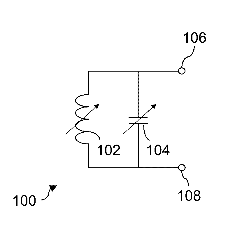
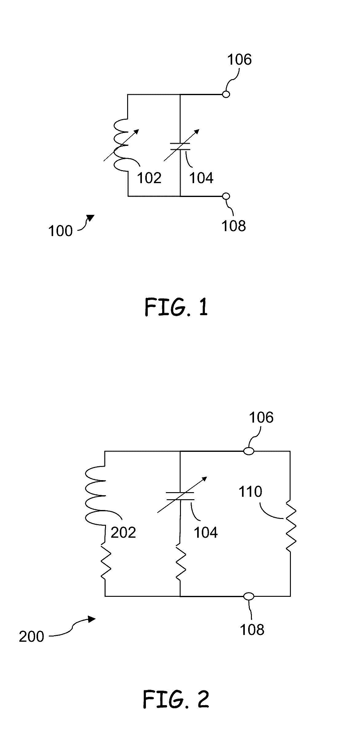
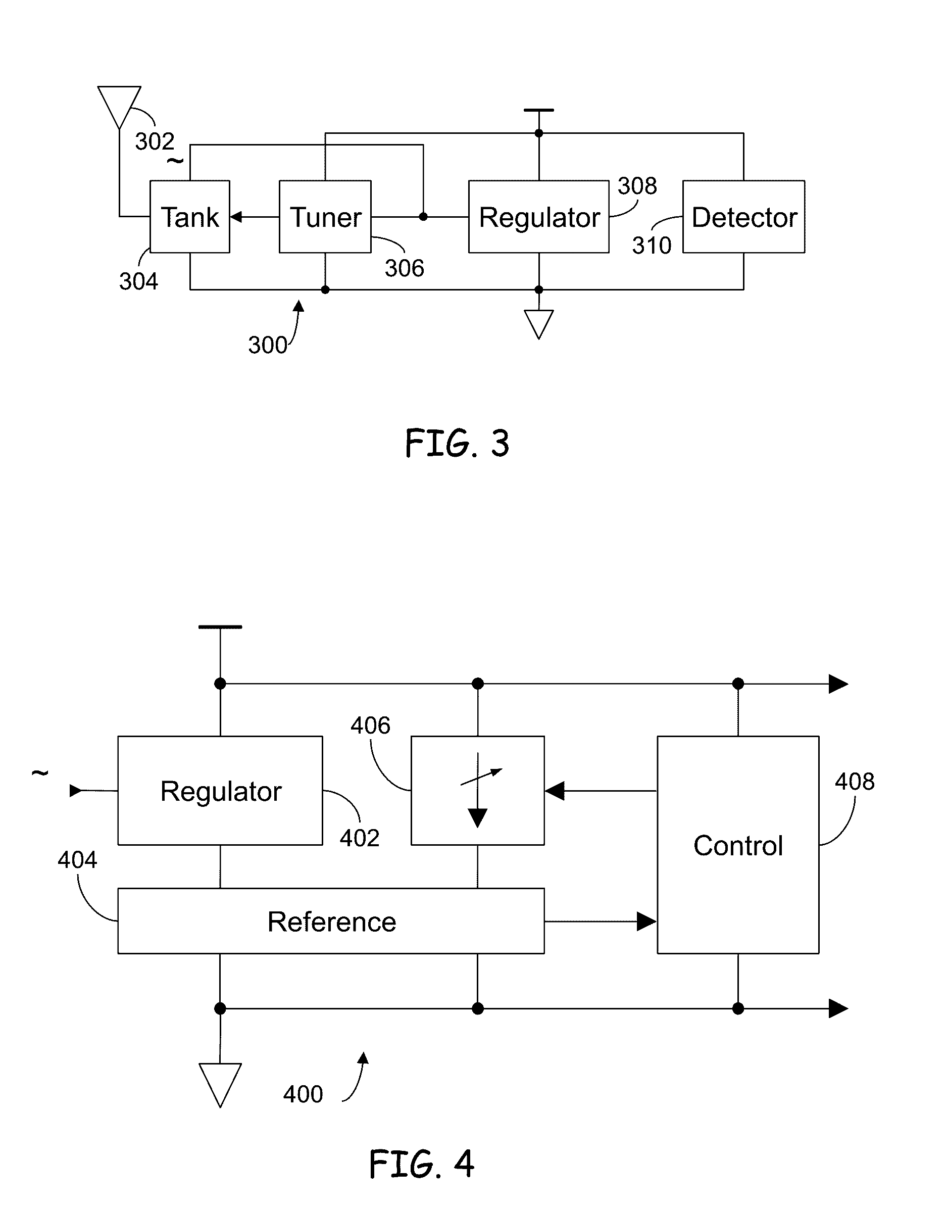
[0080]Preferred embodiments of the present invention are illustrated in the FIGs., like numerals being used to refer to like and corresponding parts of the various drawings.

[0081]Throughout this description, the terms assert and negate may be used when referring to the rendering of a signal, signal flag, status bit, or similar apparatus into its logically true or logically false state, respectively, and the term toggle to indicate the logical inversion of a signal from one logical state to the other. Alternatively, reference may be made to the mutually exclusive Boolean states as logic 0 and logic 1. Of course, as is well known, consistent system operation can be obtained by reversing the logic sense of all such signals, such that signals described herein as logically true become logically false and vice versa. Furthermore, it is of no relevance in such systems which specific voltage levels are selected to represent each of the logic states.

[0082]Embodiments of the present disclosur...


PUM


Abstract

A passive radio frequency identification (RFID) sensor is provided. This passive RFID sensor includes at least one antenna, at least one processing module, and a wireless communication module. The at least one antenna has an impedance that may vary with an environment in which the sensor is placed. Additionally, the antenna impedance might be permanently changed in response to an environmental variation or an event. The at least one processing module couples to the antenna and has a tuning module that may vary a reactive component impedance coupled to the antenna in order to change a system impedance. The system impedance includes both the antenna impedance and the reactive component impedance. The tuning module then produces an impedance value representative of the reactive component impedance. A memory module may store the impedance value which may then later be communicated to an RFID reader via the wireless communication module. The RFID reader may then exchange the impedance value representative of the reactive components of impedance with the RFID reader such that the RFID reader or another external processing unit may process the impedance value in order to determine environmental conditions at the inductive loop. These environmental conditions may include but are not limited to temperature, humidity, wetness, or proximity of the RFID reader to the passive RFID sensor.

Description

RELATED APPLICATIONS[0001]This application claims priority under 35 USC §119(e) to, and hereby claims benefit of the filing dates thereof pursuant to 37 CFR §1.78(a)(4) of the following U.S. Provisional Patent Applications:[0002]1. U.S. Provisional Application Ser. No. 62 / 057,186, filed 29 Sep. 2014, (Entitled: “RADIO FREQUENCY IDENTIFICATION (RFID) TAG(S) and SENSOR(S)”);[0003]2. U.S. Provisional Application Ser. No. 62 / 057,187, filed 29 Sep. 2014, (Entitled: “METHOD AND APPARATUS FOR IMPEDANCE MATCHING USING DITHERING”);Additionally, the above identified U.S. Provisional Patent Applications and their subject matter are expressly incorporated by reference in their entirety and made part of the present U.S. Utility Patent Application for all purposes.BACKGROUND OF THE INVENTION[0004]1. Field of the Invention[0005]The present invention relates generally to sensing a detectable environmental condition, and, in particular, to sensing a detectable environmental condition in a passive RF...

Claims


Application Information

Patent Timeline
IPC IPC(8): G06K7/10G06K19/07
CPCG06K7/10148G06K7/10326G06K19/0726G06K19/0716G06K19/0717H01Q5/335G06K19/07788H01Q1/2225
Inventor ROKHSAZ, SHAHRIARYOUNG, BRIAN DAVIDYOUNIS, AHMEDPAULOS, JOHN J.MISRA, ABHAYCOOKE, BENJAMINHASSOUN, MARWAN
Owner RFMICRON
Why Eureka
Try Eureka