Automatic detection of defects in composite structures using ndt methods

a composite structure and automatic detection technology, applied in the field of automatic detection of defects in composite structures using ndt methods, can solve the problems of estimating the type of damage, reducing the detection accuracy, and reducing the cost of the proj

Inactive Publication Date: 2016-11-10
KURION INC
View PDF4 Cites 25 Cited by
  • Summary
  • Abstract
  • Description
  • Claims
  • Application Information

AI Technical Summary

Benefits of technology

[0018]The present invention is an NDT thermography method, which can be implemented in a number of apparatuses using an uncooled IR camera, to detect, identify, locate, and determine the size of defects in composite materials automatically and in real-time without having to interpret raw IR images. The system was motivated by the need to inspect a variety of military and commercial aircraft structures, which structures include honeycomb structures with aluminum or composite surface skins, tongue and groove gridlock structures, and composite structures comprised of various composite and core layers. The method works on any type of composite materials. The preferred embodiment is comprised of an uncooled IR camera, a heating or cooling method to change the temperature of the composite structure relative to the ambient temperature in such a way as to produce detectable IR intensity changes in the region of the defect, an electronic ruler to determine the coverage and location of the IR images and any defects detected on the composite structure, a computer to collect, process, and output the results as the NDT inspection is being performed. Only a small temperature change in the surface of the composite structure is needed to produce detectable IR signals, and heating the surface for a short time period (e.g., 10 s) will suffice. A silicone heating mat, which conductively heats the surface of the composite, is the preferred heating method, but convective and radiant heating and cooling methods are equally effective. The processing includes removal of the background noise, including the IR response from uneven heating, using a noise cancellation method based on a median filter. The coverage and location of any defects on the composite structure is done automatically using a special IR Ruler, which is placed on the composite structure before the measurements are made. The IR camera and heating method can be implemented as an integrated stand-alone system on a frame, or as separate handheld units. The entire inspection can be performed automatically without the need for the operator to manually interpret IR images or manually locate the defects and the area covered on the composite structure.

Problems solved by technology

Reliable damage assessment for these structures, especially aircraft structures, which are subject to wear and tear, including extreme operational conditions, is one of the most serious and costly problems faced in the field of maintenance.
This problem is compounded by the fact that damage can occur in many different forms.
Damage in composites can be detected in numerous ways, but the conventional detection methods are frequently limited to certain kinds of materials and structural geometries, and they are usually weak at quantifying the type of damage.
This increases the labor costs and adds to the time needed to complete the inspection.
For these reasons, NDT inspection using thermography, which has been around for many years, has not gained the same acceptance and market share as some of the other methods.
This is a problem, because themography can detect and identify all of the defects of interest, which is not possible with many of the other methods.
Such measurements are not possible with x-ray methods.
While x-ray methods can detect the presence of water or moisture in a honeycomb structure, but they cannot differentiate the water or moisture from a buildup of epoxy that can be done with thermography methods.
Acoustic methods, which require the application (and cleanup) of gel to the surface before making point measurements with a small probe, are operationally messy and slow.

Method used


Image

  • Automatic detection of defects in composite structures using ndt methods
  • Automatic detection of defects in composite structures using ndt methods
  • Automatic detection of defects in composite structures using ndt methods

Examples


Embodiment Construction

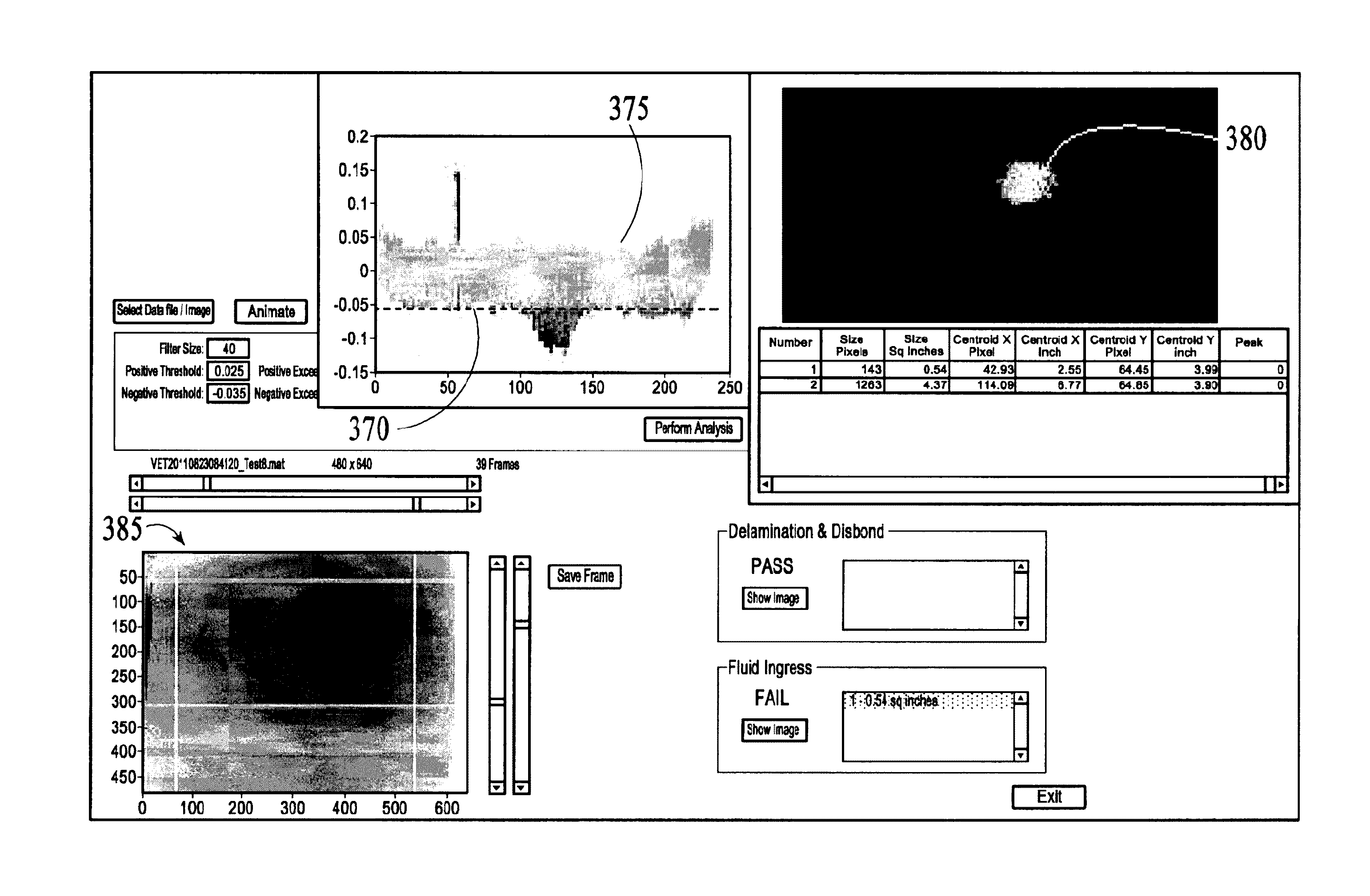
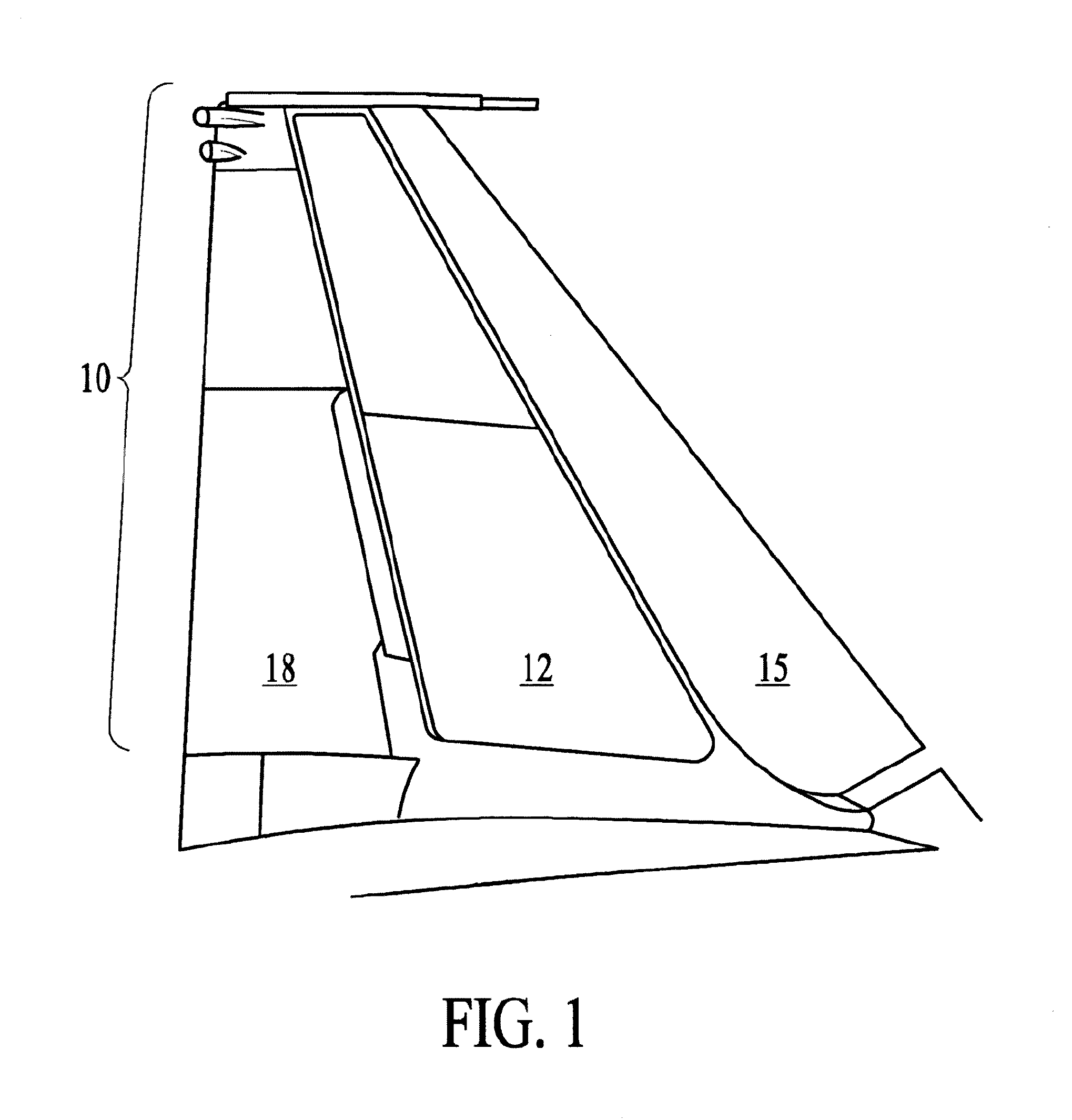
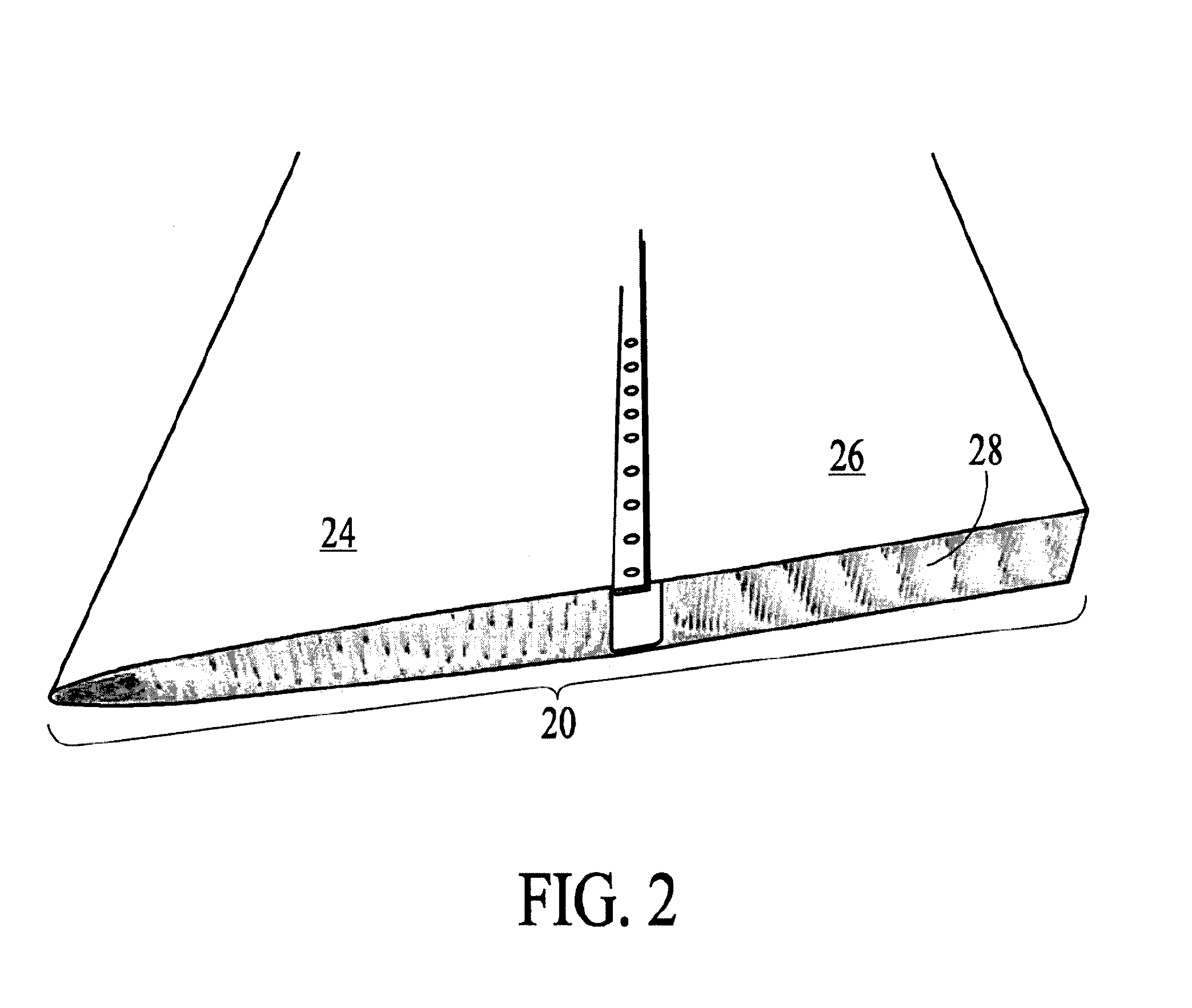
[0081]The method and apparatus of the preferred embodiment of the present invention (IRIS) is illustrated in FIG. 4 as it is applied to inspection of the aluminum honeycomb boron composite structures found in the vertical stabilizer of an F-15 jet aircraft like the one shown in FIG. 2. FIG. 5 illustrates an alternative embodiment, a handheld version of the system (i.e., referred to handheld IRIS), which was shown in FIG. 4 and being used in an inspection in FIG. 3. In this case, neither the IR camera nor the conductive heating mat is attached to the frame. The main purpose of the frame is to make it easier to position and orient the camera with respect to the composite surface. This positioning and orientation is now done using photogrammetry methods using the reference fiducials on the IR Ruler, which must be present in the IR images actually used for the NDT inspection. The IR ruler may be larger and more complicated when inspecting larger composite structures. Since the IR camera...


PUM


Abstract

A method and an apparatus for automatically collecting and processing nondestructive test (NDT) data to determine the presence, type, location, size, and strength of defects in composite, honeycomb, and grid structures like those found in aircraft, wind blades, boats, cars, building structures. The preferred embodiment is comprised of an uncooled IR mounted on a frame, a conductive heating mat, an IR Ruler with fiducials in a recognizable pattern, a computer, a processor, and output displays. The data collection, processing, and display output can be controlled or reviewed remotely via the internet. The processing, location, and output displays can be applied to any NDT system that collects and processes a two-dimensional amplitude image (e.g., x-ray systems).

Description

CROSS-REFERENCE TO RELATED APPLICATIONS[0001]This application claims priority to U.S. Provisional Application No. 61 / 540,463 filed Sep. 28, 2011, the contents of which is incorporated herein by reference in its entirety.BACKGROUND OF THE INVENTION[0002]1. Field of the Invention[0003]Method and apparatuses for automatic, real-time nondestructive testing (NDT) of composite, honeycomb, and gridlock structures using thermography to determine the presence, type, location, size, and strength of defects in the composite structure without having to visually interpret raw IR images. The present invention is motivated by the types of composite structures found on aircraft using inexpensive, uncooled IR cameras, but the method and apparatuses apply to any structure comprised all or partially of composite materials such as wind blades, boats, cars, and building materials. The NDT method and apparatuses of the present invention are comprised of an IR camera, a heating or cooling method to change...

Claims


Application Information

Patent Timeline
Patent Type & Authority Applications(United States)
IPC IPC(8): G06T7/00G06T5/00G06T5/20H04N5/33
CPCG06T7/001H04N5/33G06T2207/10048G06T5/20G06T2207/10016G06T5/002G01N25/72G01N2021/8472G06T7/0004G06T2207/30164G01N21/8851
Inventor MARESCA, JR., JOSEPH W.LEUSCHEN, WILHELMINA C.AMMER, MARISSA L.
Owner KURION INC
Why Eureka
Try Eureka