Hedge trimmer

a technology of hedge trimmer and gear wheel, which is applied in the field of hedge trimmer, can solve the problems of reducing the rotation speed of the output shaft of the motor, reducing the efficiency of the motor, and generating unfavorable noise from the gear wheel meshing in the gear system, so as to reduce noise, maintain the efficiency of the brushless motor, and reduce the overall size

Inactive Publication Date: 2016-11-17
JENN FENG NEW ENERY CO LTD
View PDF5 Cites 14 Cited by
  • Summary
  • Abstract
  • Description
  • Claims
  • Application Information

AI Technical Summary

Benefits of technology

[0012]A primary objective of the present invention is to provide a hedge trimmer, which includes a brushless motor having an output shaft directly extending into and operably coupled with upper and lower eccentric holes in upper and lower eccentric wheels in order to drive upper and lower blades to move reciprocally relative to each other along their longitudinal direction. Hence no gear system is employed in the hedge trimmer of the present invention but the hedge trimmer can maintain the efficiency the motor, thereby reducing the noise effectively, the size and the manufacturing expense.
[0013]Another objective of the present invention is to provide a hedge trimmer, in which a washer is used to adjust the distance between one eccentric wheel and a bearing unit so as to avoid the problem of generation of overheat due to friction therebetween, thereby eliminating the overheat of the motor.
[0014]Yet another objective of the present invention is to provide a hedge trimmer, which includes a casing defining a motor chamber confined by a peripheral wall that is formed with a plurality of heat dissipation holes to enhance the heat dissipation effects.
[0020]One specific feature of the present invention resides in that the motor and the gear system employed in the conventional hedge trimmer is replaced by the brushless motor in such a manner that the output shaft of the brushless motor extends directly and is operably coupled with the eccentric holes in the upper and lower eccentric wheels so as to drive the upper and lower blades, thereby reducing the noise, an overall size and maintaining the efficiency of the brushless motor. In addition, implementation of the washer between the lower eccentric wheel and the bearing unit prevents overheating of the brushless motor during long period of activation owing to reduced friction therebetween. Moreover, the casing defines a motor chamber for installation of the brushless motor therein and the peripheral wall confining the chamber is formed with a plurality of heat dissipation hole to dissipate the heat generated during operation of the motor.

Problems solved by technology

Some disadvantages resulted from the conventional hedge trimmer resides in that:
The reduced rotation speed of the output shaft of the motor via the gear system lowers the efficiency of the motor.
The meshing of gear wheels in the gear system generates unfavorable noise.
Since the gear system occupies a relatively large space in the conventional hedge trimmer, the latter is bulky in size and cause large manufacturing expense.
Since the rear end of the output shaft of the motor is disposed in a bearing unit, and since the latter is directly contact with the eccentric wheel, undesired heat and friction will be generated therebetween during operation of the conventional hedge trimmer, which sometimes hinder operation of the conventional hedge trimmer.

Method used


Image

  • Hedge trimmer
  • Hedge trimmer
  • Hedge trimmer

Examples


Embodiment Construction

[0026]The accompanying drawings are included to provide a further understanding of the invention, and are incorporated in and constitute a part of this specification. The drawings illustrate embodiments of the invention and, together with the description, serve to explain the principles of the invention.

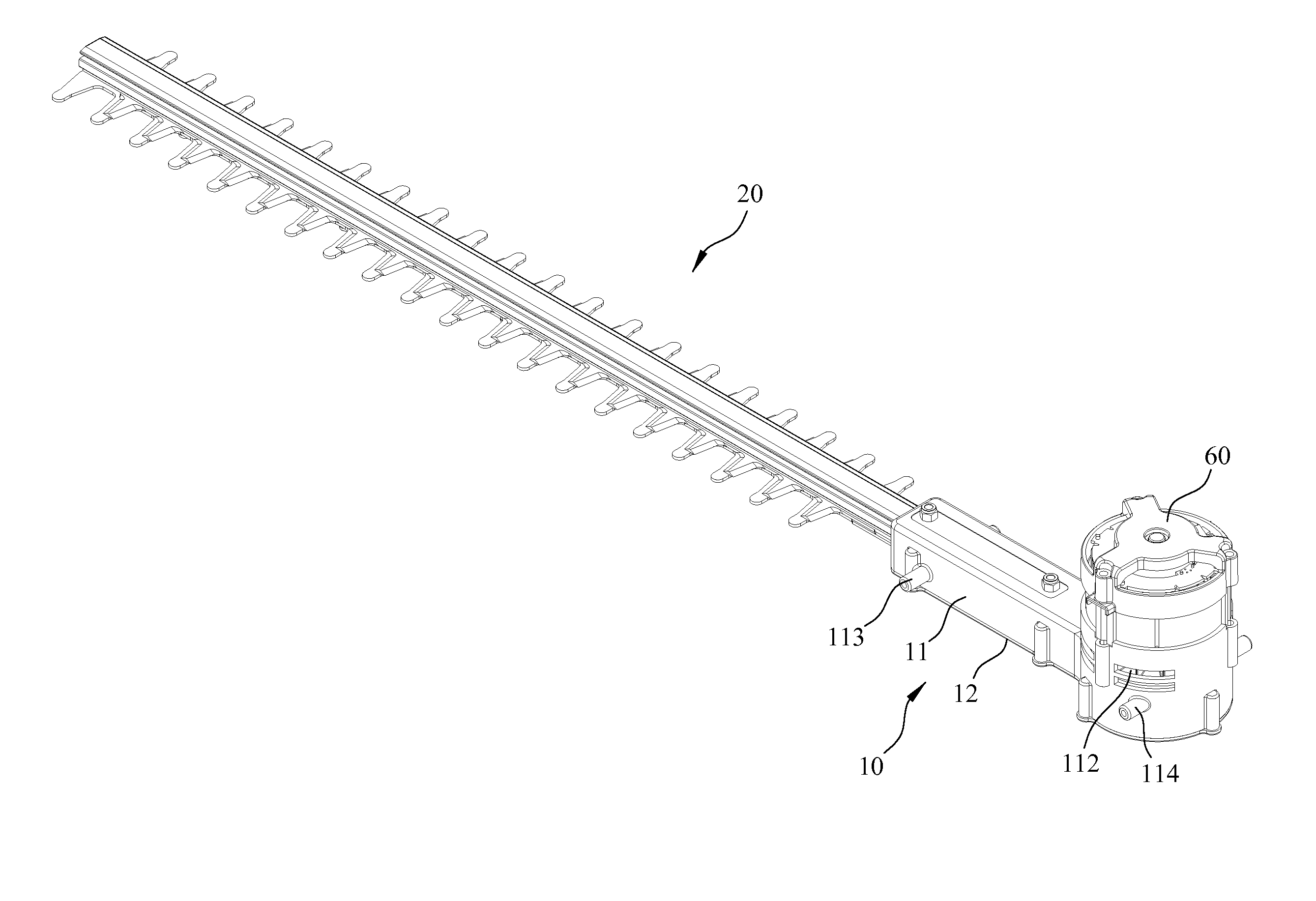
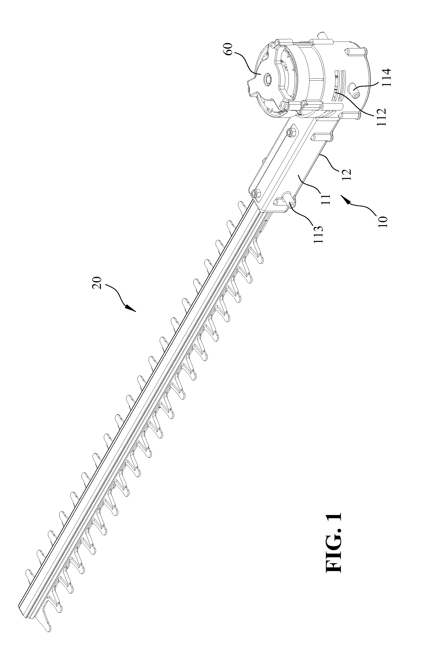
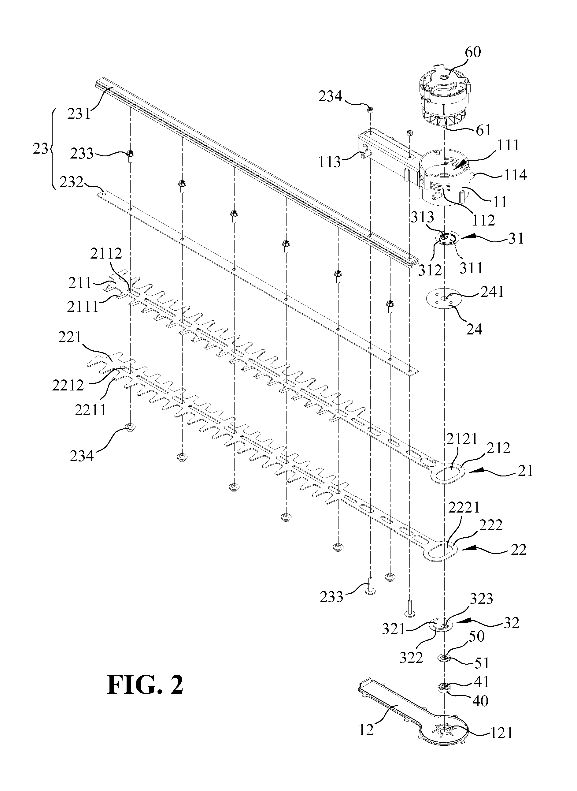
[0027]Referring to FIGS. 1 and 2, wherein, FIG. 1 is a perspective view of a hedge trimmer of the present invention while FIG. 2 is an exploded view the hedge trimmer of the present invention. As illustrated, the hedge trimmer of the present invention includes a casing 10, a cutting device 20, a cam mechanism, a bearing unit 40, a washer unit 50 and a brushless motor 60.

[0028]The casing 10 is constituted by upper and lower half casings 11, 12 which are coupled securely relative to each other. The upper half casing 11 defines a motor chamber 111 for receiving the brushless motor 60 therein. The motor chamber 111 has a peripheral wall confining the chamber and is formed with two heat d...


PUM


Abstract

A hedge trimmer includes elongated upper and lower blades overlapping relative to each other, each of the blades including a trimming portion having an outer periphery formed with a plurality of trimming edges and a mounting portion formed with a guiding hole; upper and lower eccentric wheels that extend into the guiding holes of the blades and that is formed with an eccentric hole respectively; and a brushless motor including an output shaft extending into and operably coupled with the eccentric holes in the eccentric wheels such that activation of the motor results in rotation of the eccentric wheels within the guiding holes in the blades, thereby driving the blades reciprocally relative to each other along their longitudinal direction.

Description

BACKGROUND OF THE INVENTION[0001]1. Field of the Invention[0002]The present invention relates generally to a hedge trimmer, and more particularly to a hedge trimmer including a cutting device consisting of upper and lower blades which overlap relative to each other and which are movable reciprocally relative to each other along their longitudinal direction so as to cut off partial portion of a row of shrubs, bushes, or trees, simply a hedge.[0003]2. The Prior Arts[0004]A hedge trimmer is a tool for trimming bushes of gardens in order to provide decent looking of the gardens. A conventional hedge trimmer generally includes a motor and a gear system to reduce the rotation speed of an output shaft of the motor in order to provide high torque to upper and lower eccentric wheels for driving overlapping upper and lower blades to move reciprocally relative to each other along their longitudinal direction, thereby cutting off partial sections of the hedge or trees. Hence, the garden or hedg...

Claims


Application Information

Patent Timeline
Patent Type & Authority Applications(United States)
IPC IPC(8): A01G3/053
CPCA01G3/053A01G2003/0461
Inventor TANG, YUNG-CHUN
Owner JENN FENG NEW ENERY CO LTD
Why Eureka
Try Eureka