
Chip assembly for use in a microfluidic analysis system

a microfluidic analysis and chip assembly technology, applied in the direction of analytical material containers, laboratory equipment, lamination apparatus, etc., to achieve the effects of high precision, low cost, and high precision

Active Publication Date: 2016-11-17
SOPHION BIOSCI
View PDF3 Cites 0 Cited by
  • Summary
  • Abstract
  • Description
  • Claims
  • Application Information

AI Technical Summary

Benefits of technology

The patent describes a way to integrate a chip into a larger carrier structure, which can reduce the cost and complexity of manufacturing the chip. The chip is placed into a cavity in the carrier and is sealed with a bonding material to create a secure connection. This allows for the placement of electrodes or sensor elements in the carrier, rather than on the chip itself, which can make the chip smaller and cheaper to manufacture. The carrier structure, which acts as a support for the chip, can be made from a less costly material than the chip, which can save manufacturing costs.

Problems solved by technology

The dimensions of silicon chips for use in microfluid analysis systems have hitherto been governed, at least partly, by limitations in methods of manufacture there for.

Method used


Image

  • Chip assembly for use in a microfluidic analysis system
  • Chip assembly for use in a microfluidic analysis system
  • Chip assembly for use in a microfluidic analysis system

Examples


Embodiment Construction

[0035]Embodiments of the invention will now be further described with reference to the accompanying drawings, which are provided by way of illustration only, and which are not limiting on the scope of the appended claims.

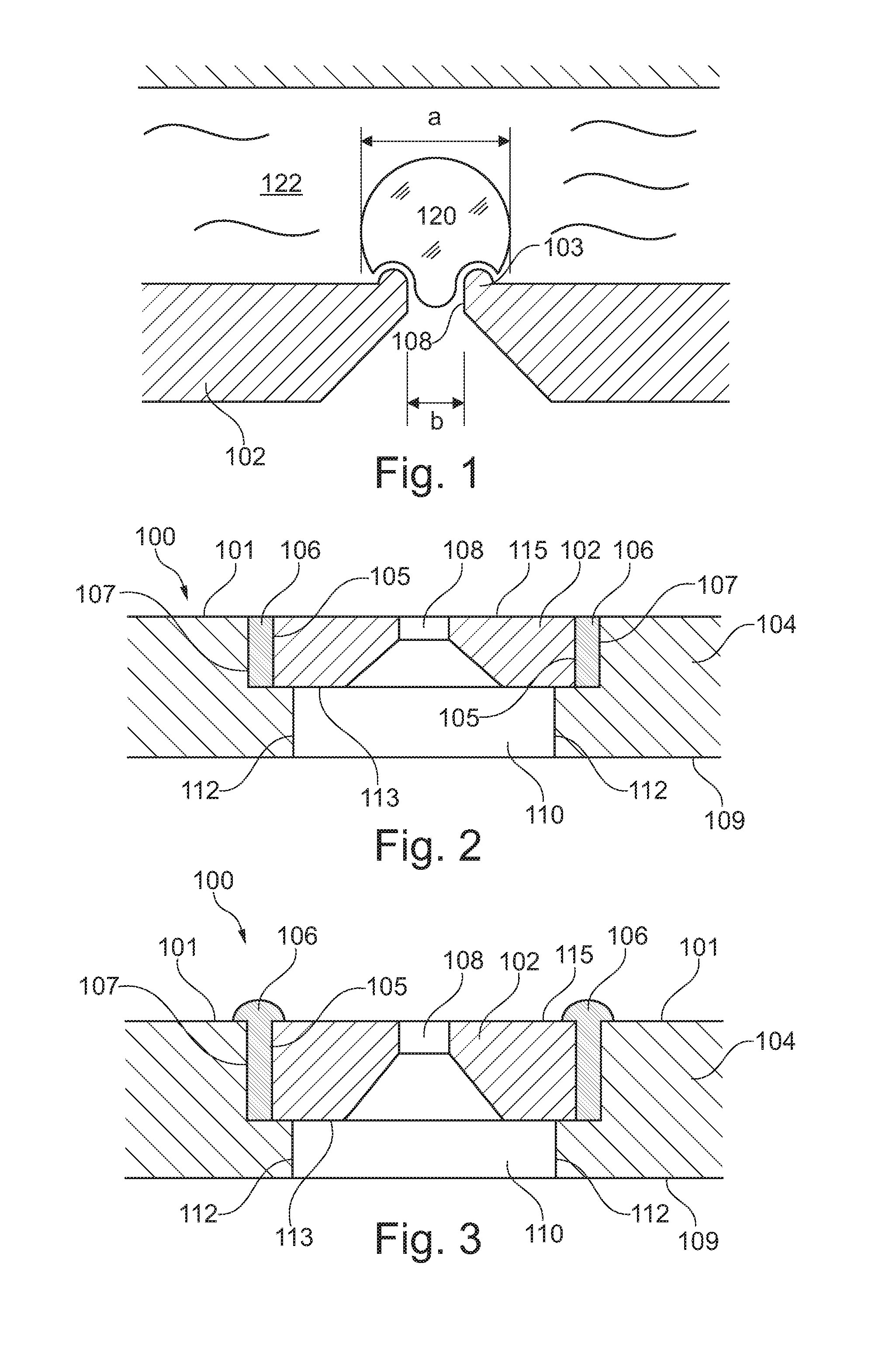
[0036]FIG. 1 shows a chip 102 for use in patch clamp analysis of a cell 120 sealed to the chip 102 at protrusion 103, which forms a gigaseal, as disclosed in WO 03 / 089564, which is hereby incorporated by reference. The chip 102 is attached to or integrated in a carrier (not shown in FIG. 1), which separates a microfluid flow domain 122 on a first side of the chip from a second domain on an opposite side thereof. The diameter a of the cell is approximately 5-20 μm, such as approximately 10 μm. A hole 108 is formed in the chip 102, through which suction may be applied to secure the cell 120 in place over the chip. Electrodes (not shown) may be provided in both of the aforementioned domains in order to determine an electrical resistance, a flow of ions or a voltage dif...


PUM

PropertyMeasurementUnit
diameteraaaaaaaaaa
areaaaaaaaaaaa
diameteraaaaaaaaaa

Abstract

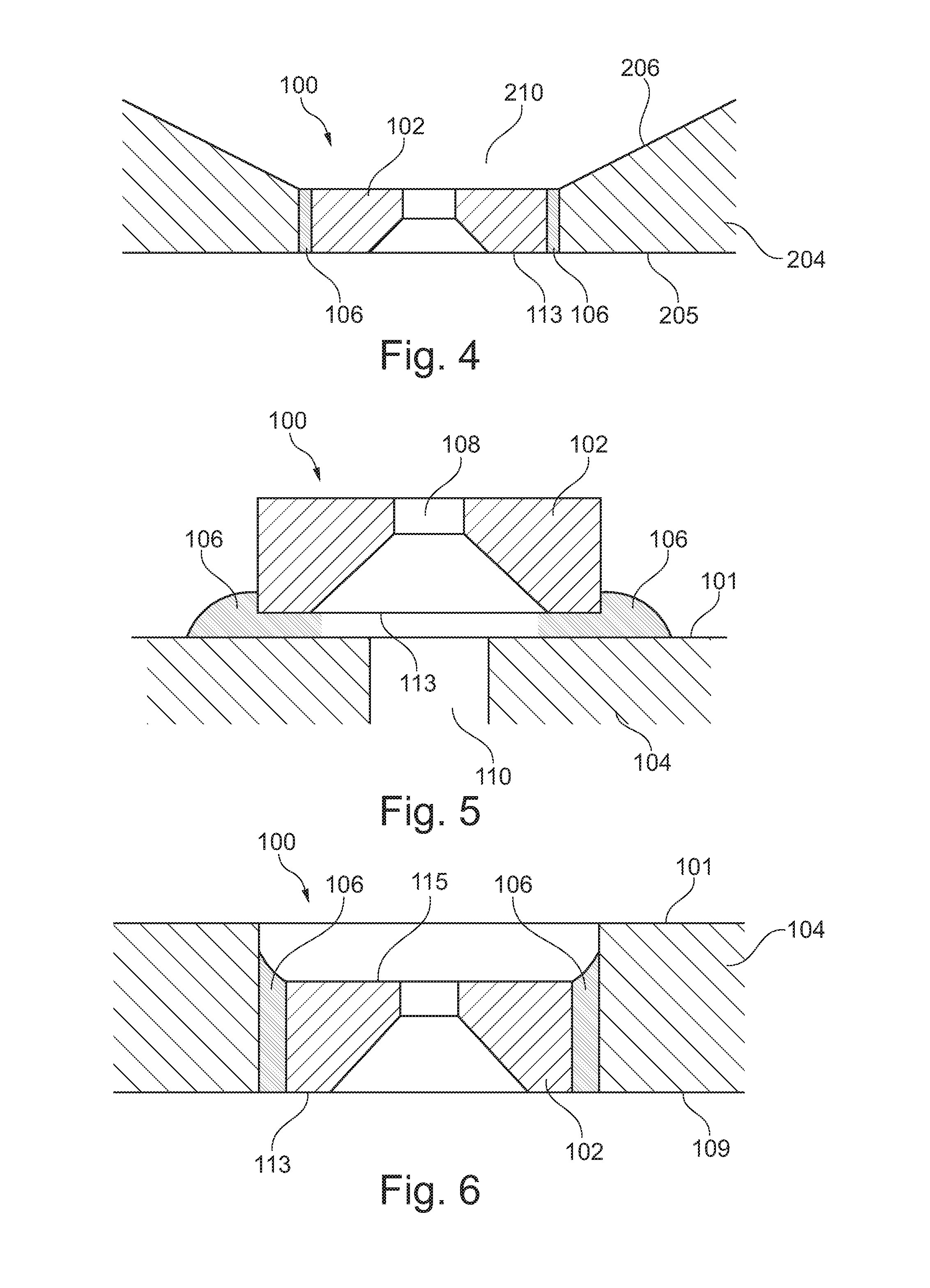
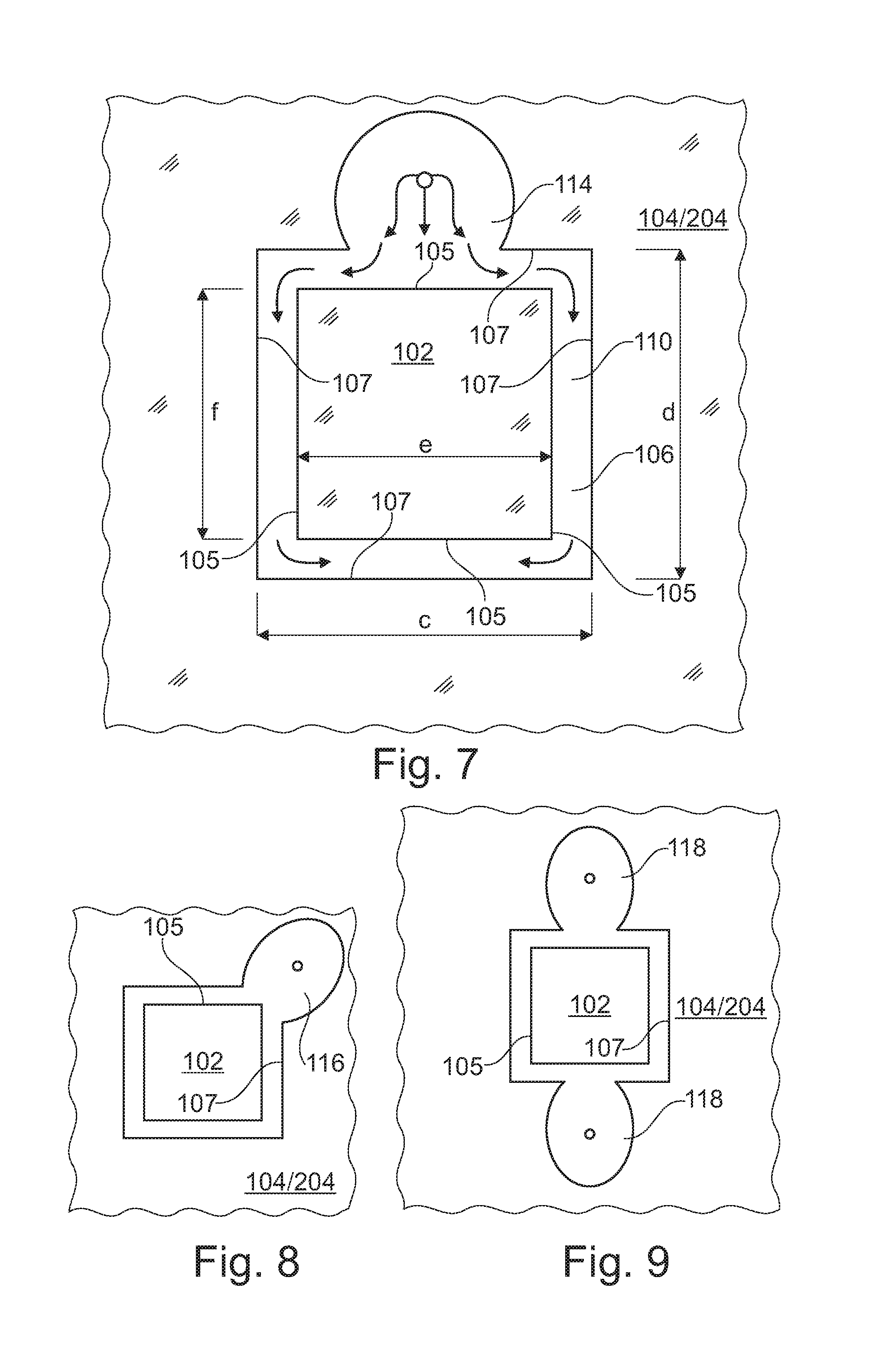
A chip assembly for use in a microfluidic analysis system, such as a patch clamp apparatus, comprises a chip having an outer wall, a carrier structure comprising an aperture for receiving the chip, the aperture defining an inner wall, wherein the chip is arranged in the aperture with a liquid tight seal between the outer wall of the chip and the inner wall of the aperture. The chip may be sealed and bonded to the carrier structure by means of a bonding material, such as an UV curing adhesive. A through hole in the chip is aligned with the aperture in the carrier structure. A method for manufacturing the chip assembly is further disclosed.

Description

CROSS REFERENCE TO RELATED APPLICATIONS[0001]This application is a Continuation of co-pending application Ser. No. 13 / 809,097, filed on 8 Jan. 2013, which is a U.S. National Stage of International Application No. PCT / EP11 / 61390 filed on 6 Jul. 2011, for which priority is claimed under 35 U.S.C. §120; and this application claims priority of application Ser. No. 11 / 157,598.1 filed in Europe on 10 Mar. 2011 under 35 U.S.C. §119; and this application claims priority of U.S. Provisional Application No. 61 / 362,926 filed on 9 Jul. 2010 under 35 U.S.C. §119(e), the entire contents of all of which are hereby incorporated by reference.TECHNICAL FIELD[0002]The present invention relates to a chip assembly for use in a microfluidic analysis system and to a method of manufacturing such a chip assembly. The integration of sensor chips in carrier plates, also referred to as microtitre plates, is of particular concern of the present invention. Embodiments of the chip assembly may provide a so-called...

Claims


Application Information

Patent Timeline
Patent Type & Authority Applications(United States)
IPC IPC(8): B01L3/00C09J5/00
CPCB01L3/502707C09J5/00B01L2200/12B01L2300/0645B01L2200/0689B01L2200/10B01L2300/0819B01L3/50B01L3/5085B32B37/1284Y10T156/10
Inventor BRASK, ANDERSKUTCHINSKY, JONATAN
Owner SOPHION BIOSCI
Learn More