Device And Method For Heating A Fluid Chamber

a fluid chamber and device technology, applied in the field of devices, apparatuses, systems and methods for heating a fluid chamber, can solve the problems of contaminating the liquid, not being easy to implement, and not being able to meet the needs of general applications, and achieves a large degree improved control of the rate of convection heat loss, and greater variation

Active Publication Date: 2016-11-17
BIOVICES IPR HLDG AS
View PDF3 Cites 3 Cited by
  • Summary
  • Abstract
  • Description
  • Claims
  • Application Information

AI Technical Summary

Benefits of technology

[0149]The gas flow is directed over the heater device to control the rate of convection heat dissipation from the heater device and the fluid container. In some embodiments this gives improved control over the rate of convection heat loss, which without the forced gas flow would depend on natural convection and so would tend to be subject to g...

Problems solved by technology

This apparatus provides a means for measurement of the volume in a PCR reaction well using a complex optical arrangement that relies on visualisation of the meniscus of the liquid in the well from above, and so is poorly suited for general applications where a fluid container may have a lid and in which the lid may be heated to provide a more uniform thermal environment inside the container.
This is disadvantageous as it requires a modified fluid container and risks contaminating the liquid.
This is particularly important if the reaction runs at high temperatures, as in the case of PCR, where evaporation...

Method used


Image

  • Device And Method For Heating A Fluid Chamber
  • Device And Method For Heating A Fluid Chamber
  • Device And Method For Heating A Fluid Chamber

Examples


embodiment 10

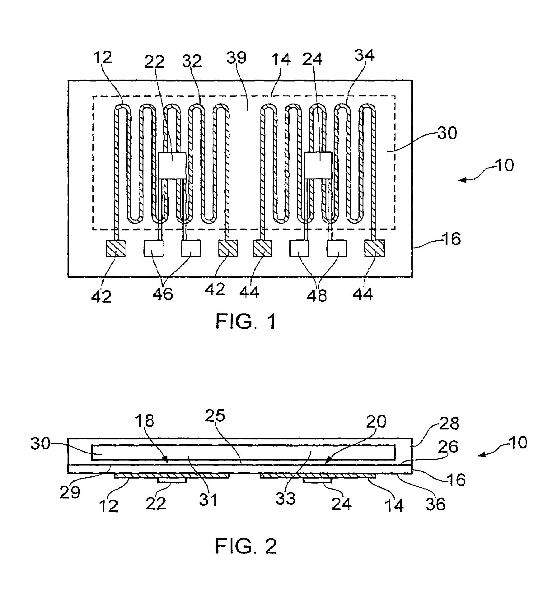
[0266]Referring to FIGS. 1 and 2, an embodiment 10 of a heater device to heat a fluid chamber comprises: a first heater 12 and a second heater 14 each disposed on a substrate 16. The first heater 12 has a first heat transfer surface 18 and the second heater 14 a second heat transfer surface 20, each heat transfer surface 18 and 20 are configured to provide thermal contact with a common fluid chamber 30. A first temperature sensor 22 is in thermal communication with the first heater 12. A second temperature sensor 24 is in thermal communication with the second heater 14. It is apparent that the second heater 14 and second temperature sensor 24 are spaced apart from the first heater 12 and the first temperature sensor 24 by a gap 39. The first heater 12 is configured to heat a first region 31 of the fluid chamber; and the second heater 14 is configured to heat a second region 33 of the fluid chamber. In this embodiment the fluid container 28 may be separable from the heater device.

[02...

embodiment 60

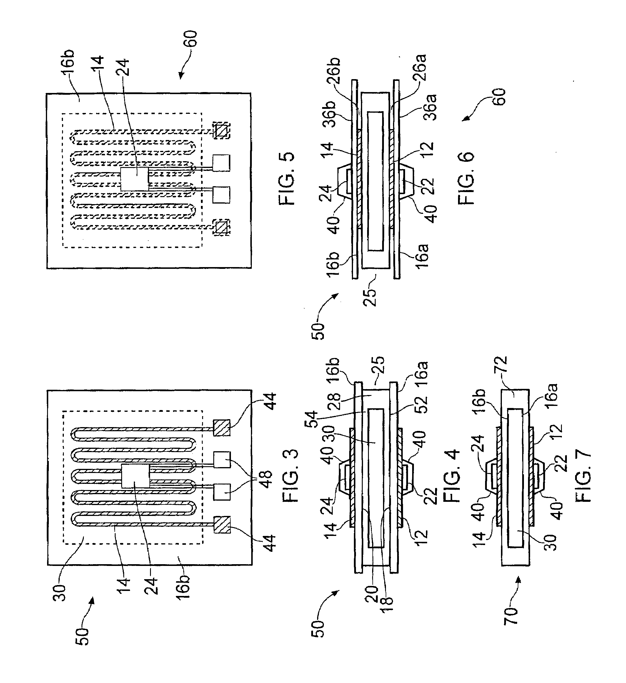
[0281]Referring to FIGS. 5 and 6, in a further embodiment 60 in which features common with embodiments 10 and 50 have common numerals, the first heater 12 is provided on the first surface 26a of the first substrate 16a and the first temperature sensor 22 is provided on the second surface 36a within the perimeter of the heated area of the first heater, and the second heater 14 is provided on the first surface 26b of the second substrate 16b and the second temperature sensor 24 is provided on the second surface 36b within the perimeter of the heated area of the second heater. In this embodiment the substrates 16a, 16b provide a region between each heater and the corresponding sensor that has a higher thermal conductance than the thermal conductance of the fluid container plus its contents between the first and the second heaters.

[0282]In some embodiments for example as shown, the substrates are planar sheet elements having a first and a second major surface and a thickness between the...

embodiment 70

[0283]Referring to FIG. 7, in further embodiment 70 the substrates 16a, 16b form part of the walls of the fluid chamber 30, the heater device itself being mounted on the housing 72 of the fluid chamber.

[0284]Some embodiments as shown in FIGS. 1 to 7 may additionally comprise the following features: An insulation layer 40 may extend substantially over the heater and heated area of each heater as well as over the temperature sensors.

[0285]The device may comprise a first thermally conducting layer in thermal contact with the substrate and the first temperature sensor and a second thermally conducting layer in thermal contact with the substrate and the second temperature sensor. Such layers may be provided to increase the thermal conductivity between the sensor and the substrate and / or the heater. Such a layer may comprise for example a layer of copper.


PUM

PropertyMeasurementUnit
Temperatureaaaaaaaaaa
Timeaaaaaaaaaa
Flow rateaaaaaaaaaa

Abstract

The present invention relates to an apparatus, system and method for heating a fluid chamber. Devices for heating a fluid chamber, in which a temperature sensitive or temperature-initiated chemical reaction takes place, typically comprise a heater and a temperature sensor. A heater device heats a fluid container which is separable from the heater device. The device comprises one or more substrates each forming a surface of a receiving location for the fluid container. A first heater is disposed on a surface of a substrate in thermal communication with a first heat transfer surface within the receiving location. A second heater is disposed on a surface of a substrate in thermal communication with a second heat transfer surface and is spaced apart from the first heat transfer surface. A first temperature sensor is in thermal communication with the first heater and a second temperature sensor is in thermal communication with the second heater. The device is configured to conform to the shape of the fluid container such that the first and the second heat transfer surfaces come into contact with the fluid container.

Description

FIELD[0001]The present invention relates to devices, apparatus, systems and methods for heating a fluid chamber, in particular applied to a thermocycler device and method of controlling a thermocycling reaction.BACKGROUND[0002]Devices for heating a fluid chamber, in which a temperature sensitive or temperature-initiated chemical reaction takes place, typically comprise a heater and a temperature sensor. The heater is controlled thermostatically to maintain a desired temperature so that it can be sensed by the sensor. In some circumstances, a reaction requires the reactant to be exposed to two or more different temperatures sequentially. Predicting the precise amount of heat to be applied, the instant energy is to supplied and the rate of supply of energy (heat) is no always straightforward because a time constant for the response of a system depends on many factors, including the geometry and physical structure of the fluid chamber, the heater and the sensor.[0003]In particular, in ...

Claims


Application Information

Patent Timeline
IPC IPC(8): B01L7/00C12Q1/68
CPCB01L7/52C12Q1/686B01L2200/147B01L2300/021B01L2300/041B01L2300/1894B01L2200/142B01L2300/123B01L2300/0609B01L2300/1827B01L2300/0858B01L2300/1844
Inventor THOMSEN, LARS
Owner BIOVICES IPR HLDG AS
Why Eureka
Try Eureka