Supercharge Your Innovation With Domain-Expert AI Agents!

Request distribution system, management system, and method for controlling the same

a management system and request technology, applied in the field of distributing requests, can solve the problems of system difficulty in performing, description processing, and the inability to largely shift the release date of a new version of the system to a subsequent da

Active Publication Date: 2016-11-17
CANON KK
View PDF11 Cites 8 Cited by
  • Summary
  • Abstract
  • Description
  • Claims
  • Application Information

AI Technical Summary

Benefits of technology

The present invention is a system that can adjust resources for processing requests from different networks. It receives a request, determines which processing system to use, and sends the request to that system. This allows for efficient distribution of requests to processing systems and ensures that enough resources are available for processing during times when the processing systems need to switch between them. Overall, the invention improves the speed and reliability of processing requests from different networks.

Problems solved by technology

Taking the transition in the amount of requests into consideration, such a system has difficulty in performing the above-described processing system switching because the next upgrade time is close.
Further, in some cases, the release date of a system of a new version cannot be largely shifted to a subsequent date because of system operations.
Therefore, even when the first processing system is receiving a large number of requests from an external network and therefore is subjected to a large processing load, it may be necessary to start processing for switching the processing system for processing these requests aiming for the upgrade.
On the other hand, the second processing system prepared for processing system switching for upgrade has not yet received and processed a request from an external network, and therefore the resource manager has not completed the resource adjustment processing.
In this case, if the resource adjustment processing by the resource manager is slow, request processing by the second processing system may possibly be stagnated.

Method used


Image

  • Request distribution system, management system, and method for controlling the same
  • Request distribution system, management system, and method for controlling the same
  • Request distribution system, management system, and method for controlling the same

Examples


first application example

[0144]In the first and the second exemplary embodiments, the resource manager 303 generates the dispatch server 304 simultaneously with the generation of the Green environment 350 or according to the timing of the generation of the Green environment 350. In the present application example, the resource manager 303 generates the dispatch server 304 after receiving a request for starting the processing system switching processing from the system administrator, and deletes the dispatch server 304 after completing the processing system switching processing.

[0145]FIG. 13 is a sequence diagram illustrating an example of the processing system switching processing.

[0146]In step S1301, the system administrator computer 110 requests the system manager 300 to start the processing system switching processing. The system administrator may manage the execution of the processing system switching processing based on a scheduled or make a setting so as to execute the processing system switching proc...

second application example

[0163]In the first and the second exemplary embodiments and in the first application example, in steps S604 and S1305, the resource manager 303 updates the DNS record in the DNS 301 to the record indicating the reception unit 501 of the dispatch server 304. After the record has been updated in this way, the reception unit 501 of the dispatch server 304 will receive all of the requests. In the present application example, to reduce effects of a failure in setting and throughput of the dispatch server 304, the number of requests to be received by the reception unit 501 of the dispatch server 304 is set to increase step by step. The resource manager 303 enables the distribution function of the DNS 301, and increases step by step the number of requests to be received by the reception unit 501 of the dispatch server 304.

[0164]FIG. 14 is a block diagram illustrating an example of a software module configuration of the dispatch server 304. The dispatch server 304 includes the reception uni...

third application example

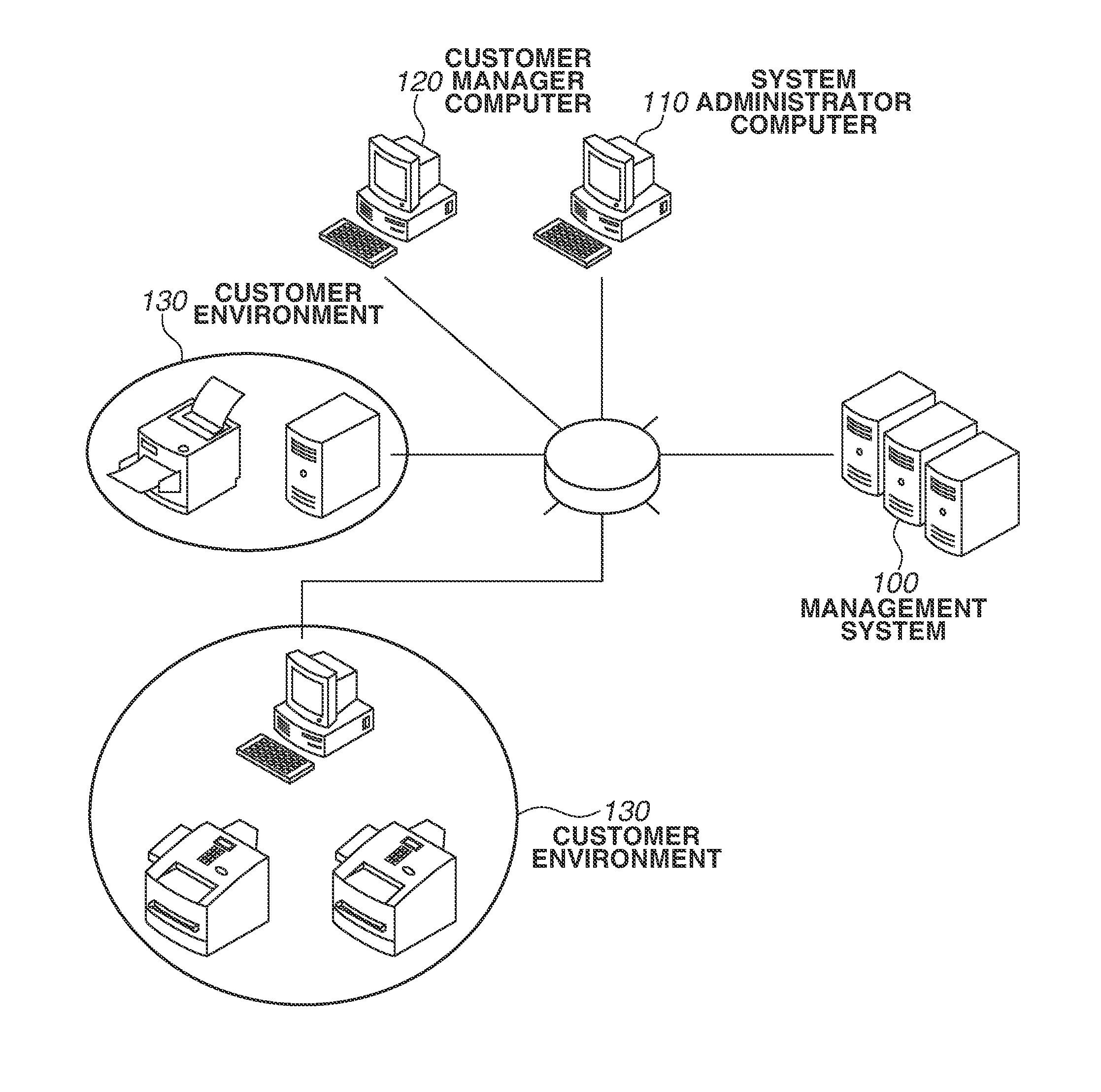
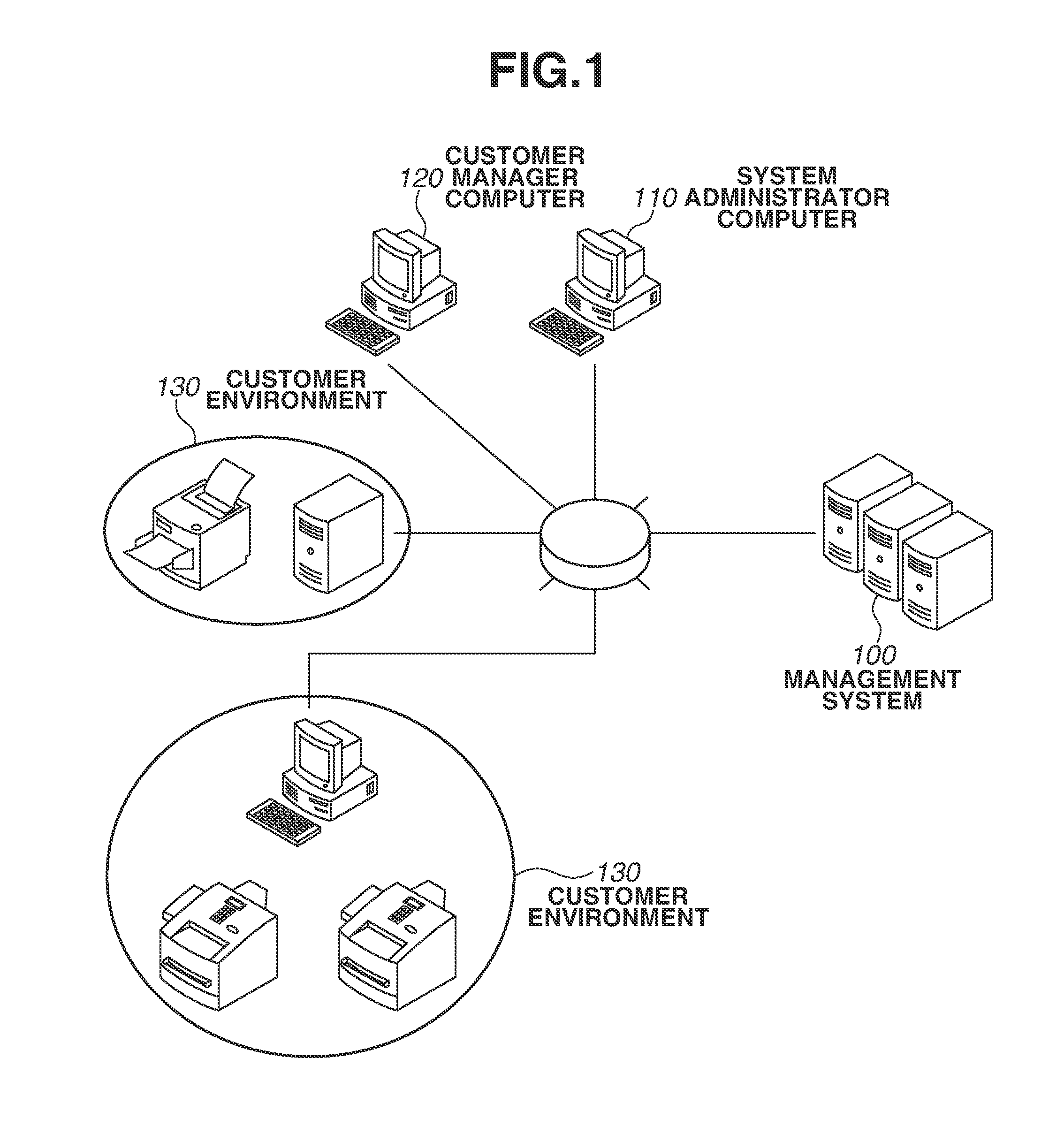
[0179]In the first and the second exemplary embodiments and in the first and the second application examples, when the customer manager computer 120 and computers in the customer environments 130 send a request to the management system 100, they hold information indicating the connection destination of the request registered in the DNS 301.

[0180]However, each time the customer manager computer 120 and computers in the customer environments 130 send a request, they do not necessarily make an inquiry to the DNS 301 about the connection destination of the relevant request. Web browsers on the customer manager computer 120 and computers in the customer environments 130 are able to hold information indicating the connection destination (e.g., IP address) for a certain fixed time period as a cache. With requests using web browsers on the customer manager computer 120 and computers in the customer environments 130, the held information may be used as a connection destination. In a time per...


PUM


Abstract

A request distribution system connected with a first and second processing system to adjust resources for use in request processing according to a received request amount includes a reception unit that receives a request, and a determination and a transmission unit. The determination unit determines a processing system as a transmission destination. The transmission unit transmits the request to the determined processing system. When a processing system for processing a request from a predetermined network system is switched from the first to the second processing system, the determination unit determines the first and second processing systems as respective transmission destinations so that the requests are distributed to the first and second processing systems between a start and end of the switching. When the second processing system is determined as the transmission destination per the amount of requests, resources to be used in the second processing system request processing are adjusted.

Description

BACKGROUND OF THE INVENTION[0001]1. Field of the Invention[0002]The present invention relates to a technique for distributing requests in a processing system during processing system switching.[0003]2. Description of the Related Art[0004]In recent years, cloud services have emerged as services for enabling the use of diverse applications operating on servers on the Internet. In such cloud services as Infrastructure as a Service (IaaS) and Platform as a Service (PaaS), a cloud service vendor provides a system administrator with resources such as virtual machines and storages via networks. A virtual machine refers to some partition or segment of a server divided or integrated in logical units regardless of the physical configuration by using virtualization technology. Each virtual machine serves as a logical computer operating based on an independent operating system. The system administrator is able to configure a system for offering original services by using virtual machines, stora...

Claims


Application Information

Patent Timeline
Patent Type & Authority Applications(United States)
IPC IPC(8): H04L12/911H04L12/24H04L29/08H04L12/947
CPCH04L47/827H04L67/325H04L41/12H04L49/25H04L67/1004H04L67/563
Inventor IMAI, KAZUO
Owner CANON KK
Features
  • R&D
  • Intellectual Property
  • Life Sciences
  • Materials
  • Tech Scout
  • Unparalleled Data Quality
  • Higher Quality Content
  • 60% Fewer Hallucinations
Learn More