Devices for vaporization of a substance

a technology of vaporization device and tobacco product, which is applied in the direction of tobacco, lighting and heating apparatus, instruments, etc., can solve the problems of inability to control the heating and combustion of existing devices, inability to produce toxic, tarry and carcinogenic by-products, and inability to control the use of existing devices

a technology of vaporization device and tobacco product, which is applied in the direction of tobacco, lighting and heating apparatus, instruments, etc., can solve the problems of inability to control the heating and combustion of existing devices, inability to produce toxic, tarry and carcinogenic by-products, and inability to control the use of existing devices

US20160338412A1Active Publication Date: 2016-11-24JLI NAT SETTLEMENT TRUST

Image

  • Devices for vaporization of a substance
  • Devices for vaporization of a substance
  • Devices for vaporization of a substance

Examples


Embodiment Construction

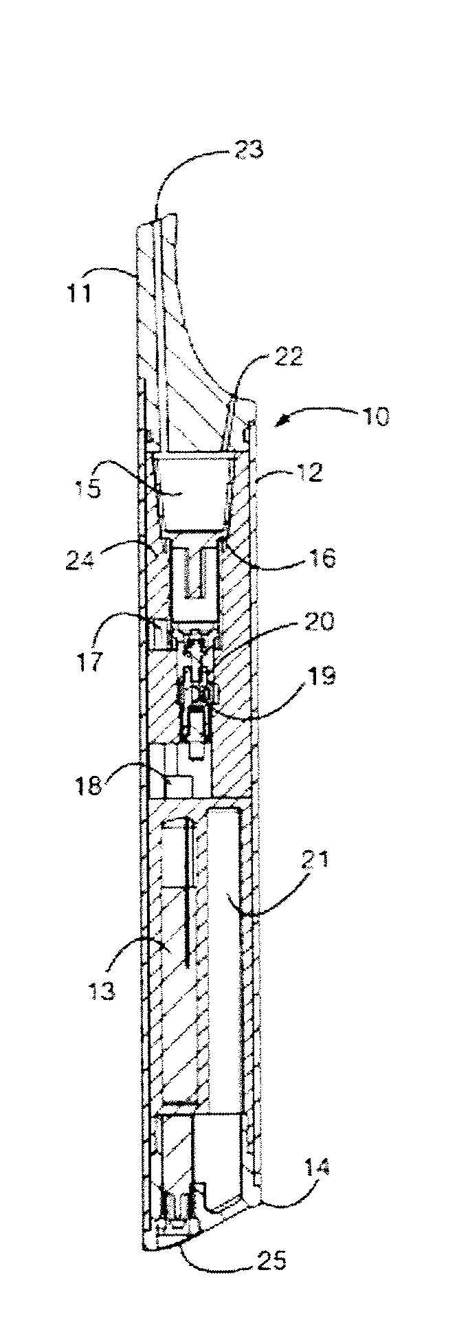
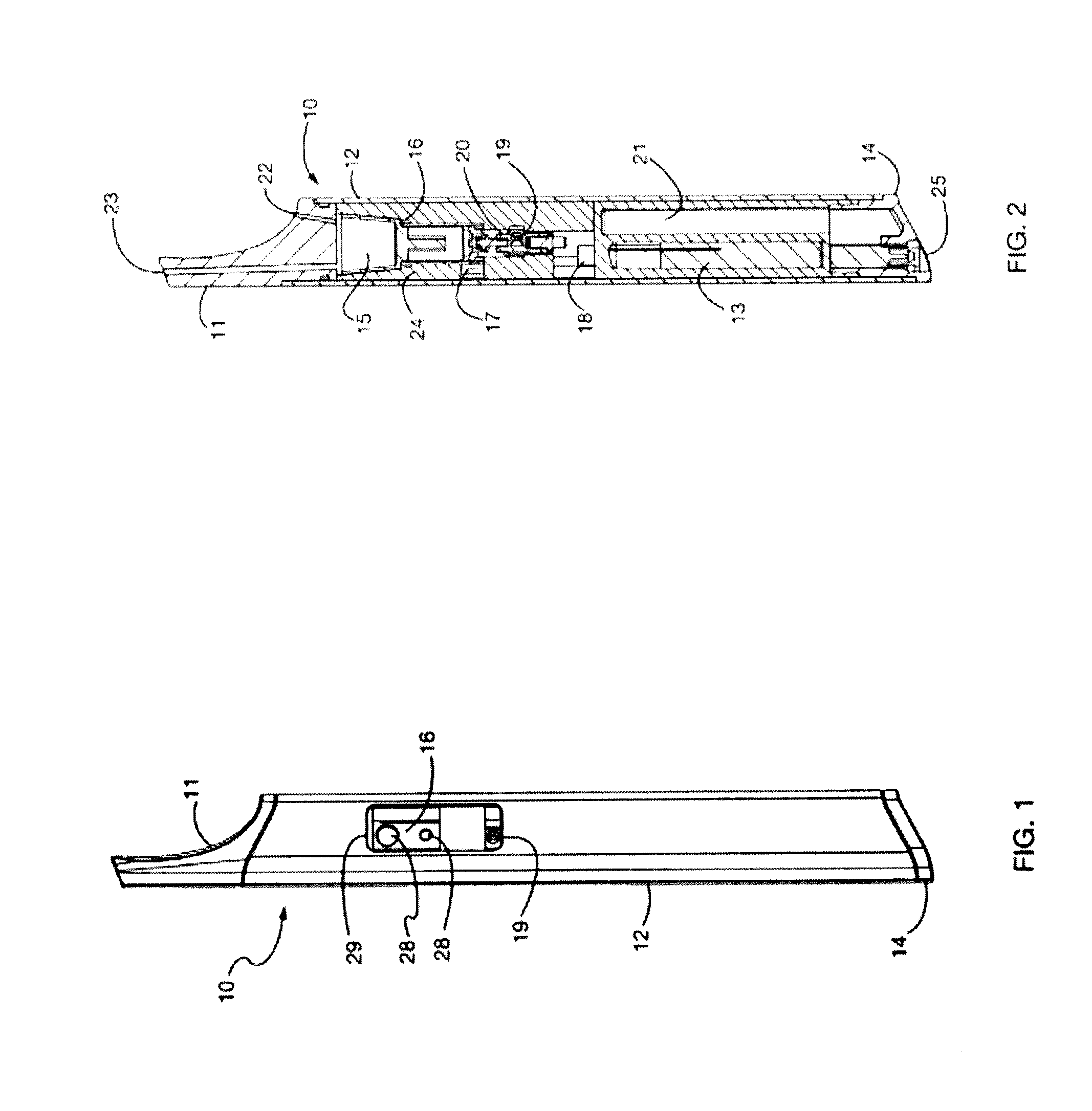
[0079]Referring to FIG. 1 and FIG. 2, the exterior of the device 10 comprises a mouthpiece 11, a tubular case 12, and the base 14 of a butane tank 21. The mouthpiece is removable and creates an airtight seal with the interior of the case. With the mouthpiece removed, a tobacco cartridge (FIG. 5) is introduced to vaporization chamber 15 of a heater 16. The mouthpiece is then reinserted to close the device. Thus, as shown in FIGS. 1 and 2, removal of the mouthpiece exposes the vaporization chamber and replacement of the mouthpiece closes the vaporization chamber.

[0080]The mouthpiece is made of a high-temperature and food-safe material such as ceramic, glass, or various high-temperature plastics such as PEI resin (brand name Ultem). Design is simplified by use of high temperature materials, but standard plastics or wood, etc., could also be used with the addition of an insulating component that prevents any excessive heat from reaching the user's lips.

[0081]To activate the device, the ...


PUM


Abstract

Devices for generating and releasing vapor. In particular, described herein are portable devices for generating a low-temperature inhalable vapor having an elongated tubular body containing a vaporization chamber and a battery-powered heater, a removable mouthpiece covering the vaporization chamber, a display configured to indicate the temperature of the vaporization chamber; a microcontroller configured to regulate the temperature of the vaporization chamber, and a control to select from among a variety of temperature settings.

Description

CROSS REFERENCE TO RELATED APPLICATIONS[0001]This application claims priority as a continuation-in-part of U.S. patent application Ser. No. 14 / 578,193, filed on Dec. 19, 2014, titled “METHOD AND SYSTEM FOR VAPORIZATION OF A SUBSTANCE”, Publication No. US 2015-0150308-A1, which is a continuation of U.S. patent application Ser. No. 11 / 485,168, filed on Jul. 11, 2006, titled “METHOD AND SYSTEM FOR VAPORIZATION OF A SUBSTANCE”, Publication No. US-2007-0283972-A1, which claims the benefit of U.S. Provisional Patent Application No. 60 / 700,105 filed on Jul. 15, 2005, tilted “METHOD AND SYSTEM FOR VAPORIZATION OF A SUBSTANCE”. Each of these patents and patent applications are herein incorporated by reference in their entirety.[0002]This application also claims priority as a continuation-in-part of U.S. patent application Ser. No. 13 / 587,416, filed on Aug. 16, 2012, titled “LOW TEMPERATURE ELECTRONIC VAPORIZATION DEVICE AND METHODS”, Publication No. US-2013-0042865-A1, which claims priority ...

Claims


Application Information

Patent Timeline
24 Nov 2016
Publication
US20160338412A1
IPC
A24F47/00; G05D23/19; G06F3/147; A24F7/02; H05B1/02; A24F40/40; A24F40/50; A24F40/60; A24F40/90; A24F42/10; A24F42/60
CPC
A24F47/008; A24F7/02; G06F3/02; G06F3/147; G05D23/1917; H05B1/0244; A24F13/04; A61M15/0028
Inventors
MONSEES, JAMES; BOWEN, ADAM