
Air conditioner

Active Publication Date: 2016-11-24
DENSO CORP
View PDF4 Cites 37 Cited by
  • Summary
  • Abstract
  • Description
  • Claims
  • Application Information

AI Technical Summary

Benefits of technology

The patent text describes improving the air-temperature control in an air conditioner by reducing the volumes of the heat-medium pipe and the heat medium between the heat-medium temperature adjuster and the heat-medium air heat exchanger. This can be achieved by using a heat-medium flow path with a smaller inner diameter. By doing so, the thermal capacity of the air conditioner can be reduced, resulting in better air-temperature control. The patent also suggests reducing the volumes of the heat-medium pipe and heat medium between the heat-medium cooling heat exchanger and the air-cooling heat exchanger for improved air-temperature control in the air-cooling heat exchanger.

Problems solved by technology

Thus, the air conditioner in the related art could degrade the response of the air-temperature control.
Especially, in quick air-heating (warming up) or quick air-cooling (cooling down) immediately after the start-up of the air-conditioning, the delay of the temperature control becomes remarkable.
However, in this case, the size of the refrigeration cycle device could increase, or the power consumption efficiency could deteriorate.

Method used


Image

  • Air conditioner
  • Air conditioner
  • Air conditioner

Examples


first embodiment

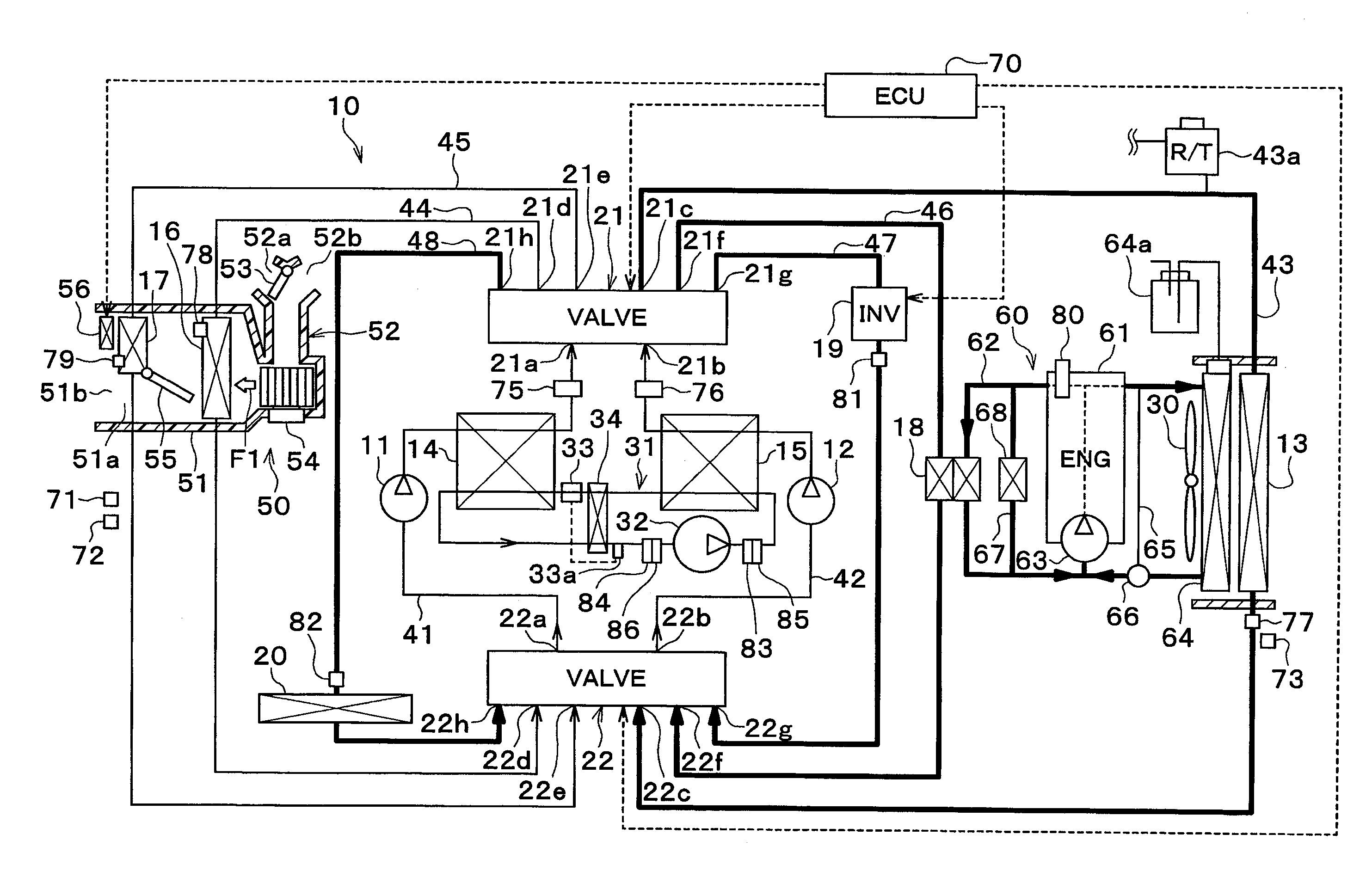
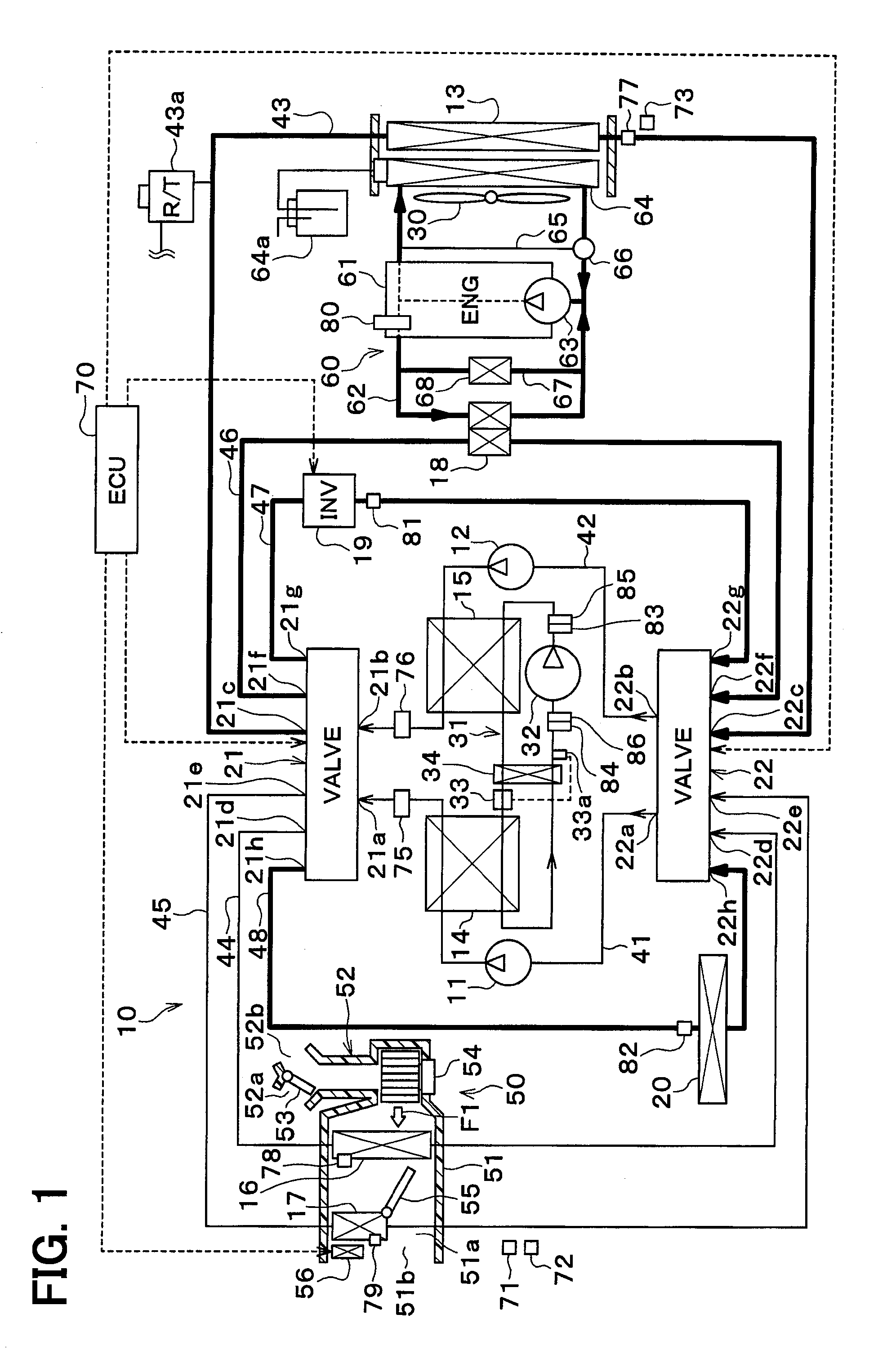
[0046]A vehicle thermal management system 10 shown in FIG. 1 is used to adjust various devices mounted on the vehicle or the vehicle interior to an appropriate temperature. In this embodiment, the vehicle thermal management system 10 is applied to a hybrid vehicle that can obtain the driving force for vehicle-traveling from both an engine (internal combustion engine) and a traveling electric motor (motor generator).

[0047]The hybrid car of this embodiment is configured as a plug-in hybrid car that can charge the battery (vehicle-mounted battery) mounted on the vehicle, with power supplied from an external power source (commercial power source) during stopping of the vehicle. For example, a lithium ion battery can be used as the battery.

[0048]The driving force output from the engine is used not only as a driving force for vehicle traveling but also for operating a power generator. Power generated by the generator and power supplied from an external power source can be stored in the ba...

second embodiment

[0218]In this embodiment, as shown in FIG. 4, the heater core 17 is disposed in the circulation flow path 62 of the engine cooling circuit 60.

[0219]The heater-core flow path 45 is coupled to the coolant outlet side of the coolant heater 15 and the coolant suction side of the second pump 12 in the second-pump flow path 42.

[0220]The heater-core flow path 45 is coupled to the coolant outlet side of the engine 61 and the coolant inlet side of the heater core 17 in the circulation flow path 62 via a three-way joint 90.

[0221]The heater-core flow path 45 is coupled to the coolant outlet side of the heater core 17 and the coolant inlet side of the engine 61 in the circulation flow path 62 via a three-way valve 91.

[0222]The three-way valve 91 is a switching device that switches between the state in which the coolant heated by the engine 61 flows through the heater core 17 and the state in which the coolant heated by the coolant heater 15 flows through the heater core 17. The operation of the...

third embodiment

[0225]In this embodiment, as shown in FIG. 5, one end of the heater-core flow path 45 is coupled to the coolant outlet side of the coolant heater 15 in the second-pump flow path 42, while the other end of the heater-core flow path 45 is coupled to the coolant suction side of the second pump 12 in the second-pump flow path 42.

[0226]A reserve tank 42a is coupled to the second-pump flow path 42. The structure and function of the reserve tank 42a are substantially the same as those of the above-mentioned reserve tank 43a.

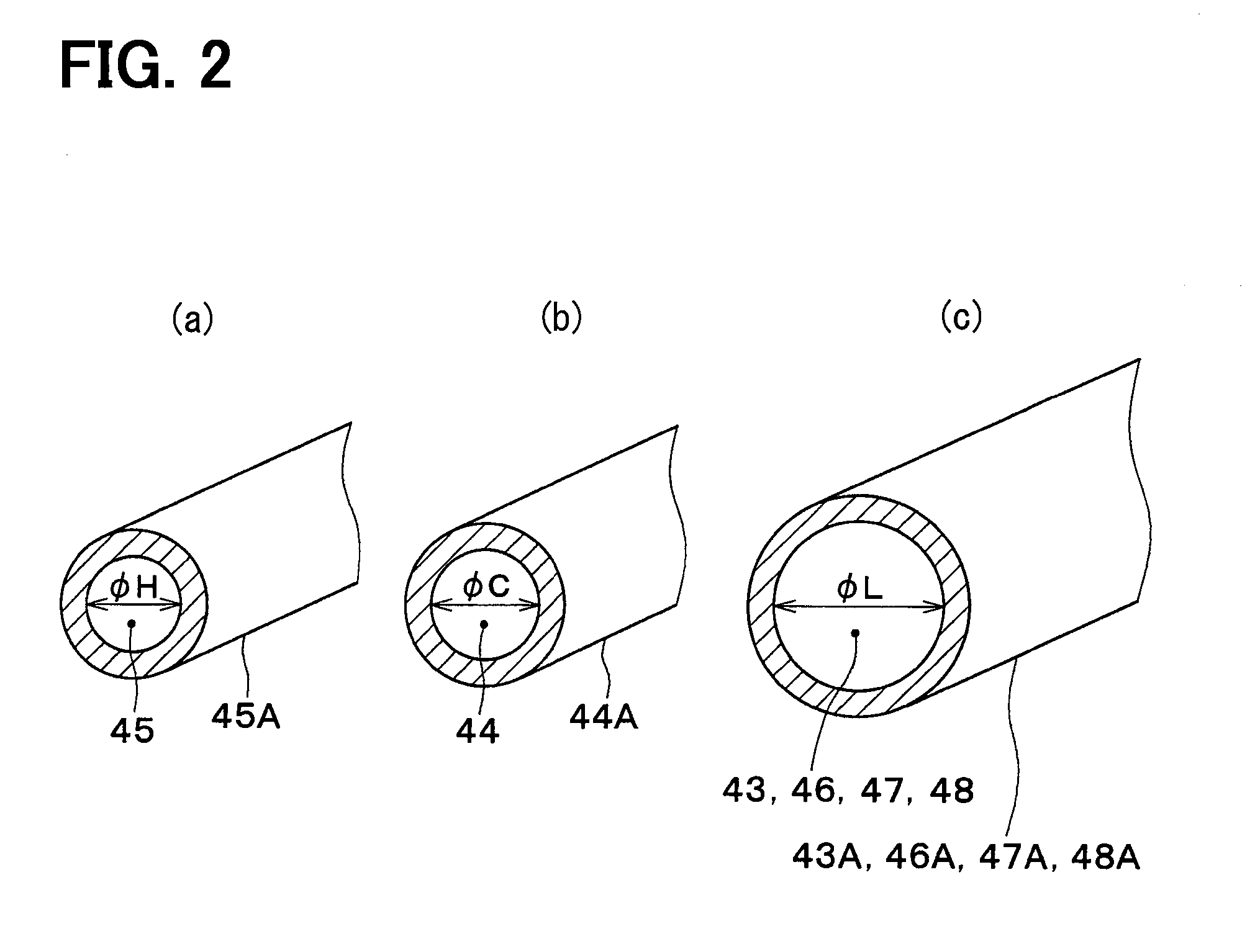
[0227]The diameter φH of the heater-core flow path 45 is set smaller than the diameter φL of each of the second-pump flow path 42 and the coolant-to-coolant heat exchanger flow path 46. In other words, the inner diameter φH of the heater-core pipe 45A forming the heater-core flow path 45 is set smaller than the inner diameter φL of each of a second-pump pipe 42A forming the second-pump flow path 42 and the coolant-to-coolant heat exchanger pipe 46A forming the coolant-...


PUM


Abstract

An air conditioner includes: a heat-medium air heat exchanger that exchanges sensible heat between a heat medium having a temperature adjusted by the heat-medium temperature adjuster and ventilation air blowing to a space to be air-conditioned; a heat transfer portion having a flow path through which the heat medium circulates to transfer heat with the heat medium having the temperature adjusted by the heat-medium temperature adjuster; a large-inner-diameter pipe that forms a heat-medium flow path between the heat-medium temperature adjuster and the heat transfer portion; and a small-inner-diameter pipe that forms a heat-medium flow path between the heat-medium temperature adjuster and the heat-medium air heat exchanger. The small-inner-diameter pipe has small inner diameters φH and φC, compared to the large-inner-diameter pipe.

Description

CROSS REFERENCE TO RELATED APPLICATION[0001]The application is based on a Japanese Patent Application No. 2014-014688 filed on Jan. 29, 2014, the contents of which are incorporated herein by reference in its entirety.FIELD OF THE INVENTION[0002]The present disclosure relates to an air conditioner that blows conditioned air into a space to be air-conditioned.BACKGROUND ART[0003]Conventionally, air conditioners for vehicles generally include refrigerant-air heat exchangers that exchange heat between the refrigerant in a refrigeration cycle and ventilation air to be blown into a vehicle compartment.[0004]On the other hand, Patent Document 1 discloses a vehicle air conditioner that includes a refrigerant-coolant heat exchanger to exchange heat between a refrigerant and a coolant in the refrigeration cycle and an air-conditioning mechanism to perform air-conditioning of the vehicle interior using the coolant having exchanged heat at the refrigerant-coolant heat exchanger.RELATED ART DOCU...

Claims


Application Information

Patent Timeline
IPC IPC(8): B60H1/00F25B25/00
CPCB60H1/00899B60H2001/00928F25B25/005F25B40/00F25B2339/047F25B2700/1931F25B2700/1933F25B2700/21151F25B2700/21152B60H1/00278B60H2001/00307B60H1/32284
Inventor ENOMOTO, NORIHIKOKAKEHASHI, NOBUHARUKUWAYAMA, KAZUTOSHIMAKIHARA, MASAMICHIYAMANAKA, TAKASHIOMI, YASUMITSUMIURA, KOJI
Owner DENSO CORP
Learn More