

Optical Image Capturing System
- Summary
- Abstract
- Description
- Claims
- Application Information
AI Technical Summary
Benefits of technology
Problems solved by technology
Method used
Image

Examples
first embodiment (embodiment 1)
The First Embodiment (Embodiment 1)
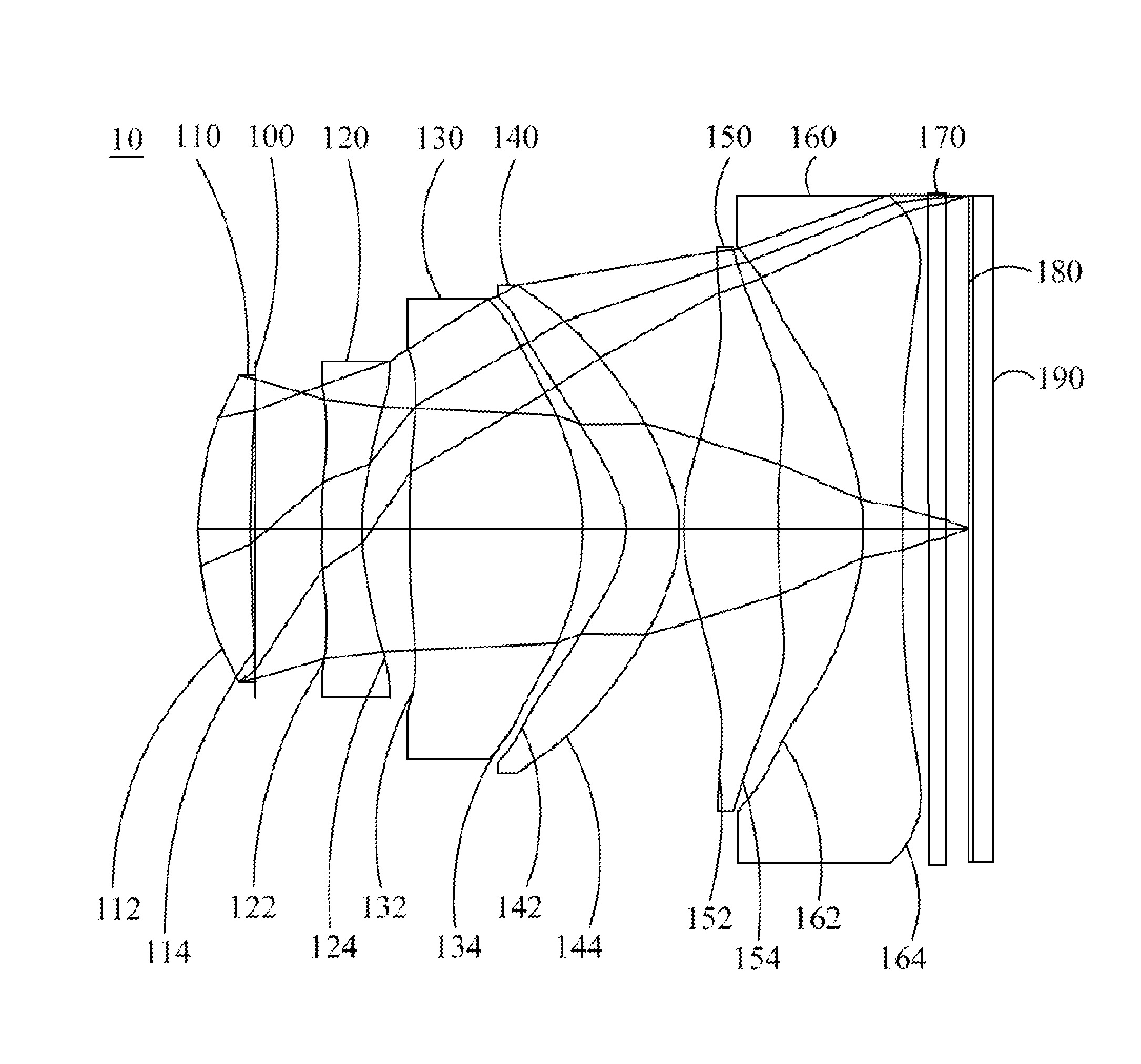
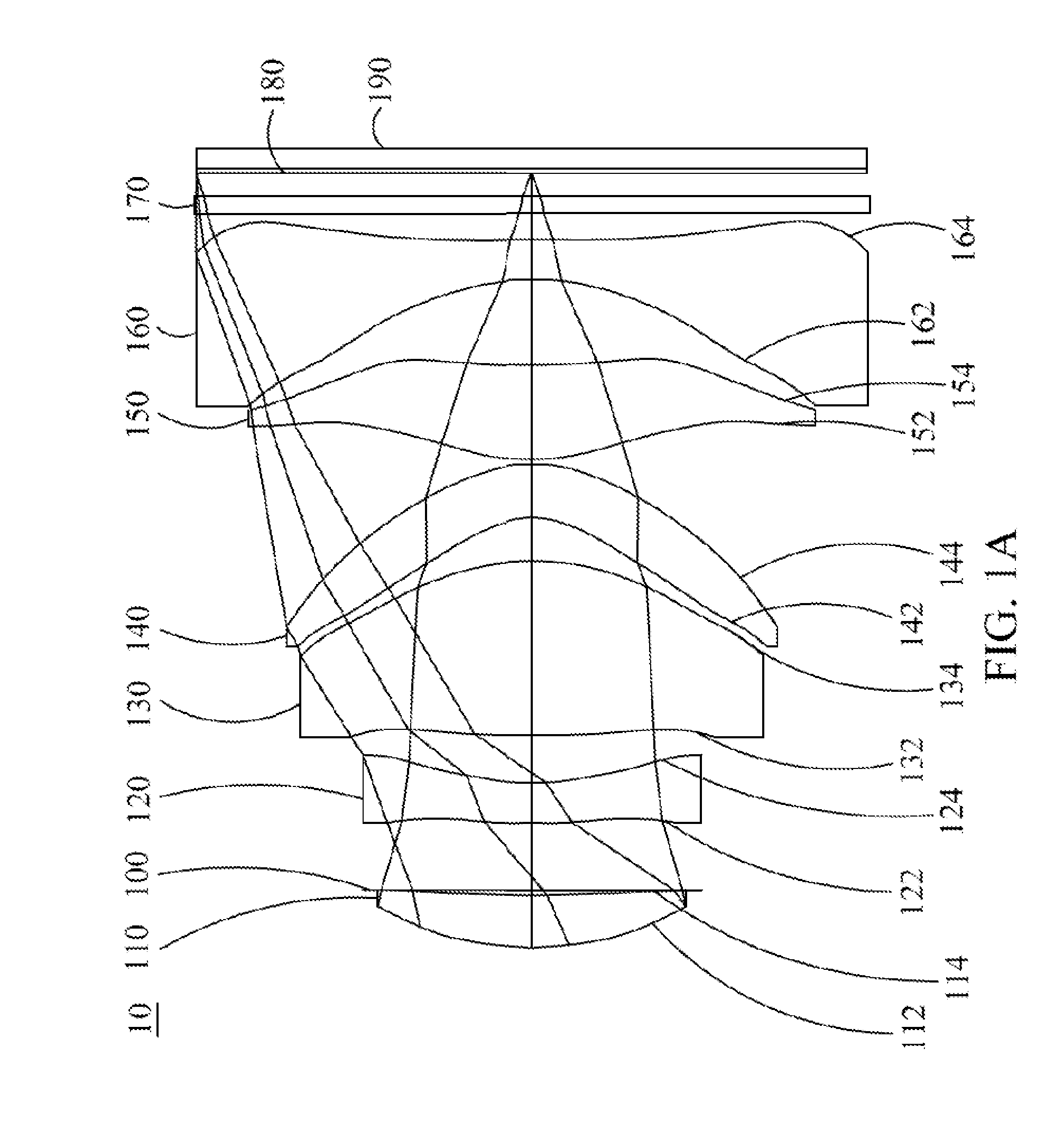
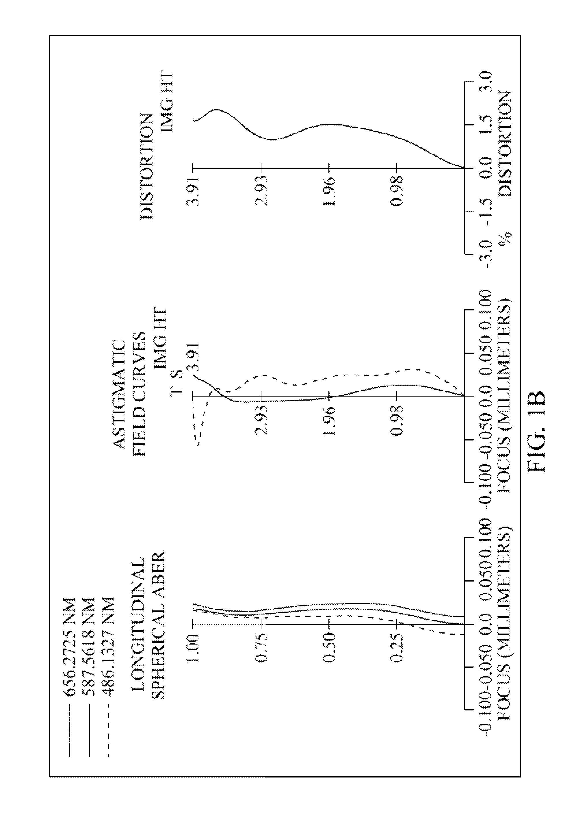
[0095]Please refer to FIG. 1A and FIG. 1B. FIG. 1A is a schematic view of the optical image capturing system according to the first embodiment of the present application, FIG. 1B is longitudinal spherical aberration curves, astigmatic field curves, and an optical distortion curve of the optical image capturing system in the order from left to right according to the first embodiment of the present application, and FIG. 1C is a lateral aberration diagram of tangential fan, sagittal fan, the longest operation wavelength and the shortest wavelength passing through an edge of the entrance pupil and incident on the image plane by 0.7 HOI according to the first embodiment of the present application. As shown in FIG. 1A, in order from an object side to an image side, the optical image capturing system includes an aperture 100, a first lens element 110, a second lens element 120, a third lens element 130, a fourth lens element 140, a fifth lens element 150,...
second embodiment (embodiment 2)
The Second Embodiment (Embodiment 2)
[0151]Please refer to FIG. 2A and FIG. 2B. FIG. 2A is a schematic view of the optical image capturing system according to the second embodiment of the present application, FIG. 2B is longitudinal spherical aberration curves, astigmatic field curves, and an optical distortion curve of the optical image capturing system in the order from left to right according to the second embodiment of the present application, and FIG. 2C is a lateral aberration diagram of tangential fan, sagittal fan, the longest operation wavelength and the shortest wavelength passing through an edge of the entrance pupil and incident on the image plane by 0.7 HOI according to the second embodiment of the present application. As shown in FIG. 2A, in order from an object side to an image side, the optical image capturing system includes first lens element 210, a second lens element 220, an aperture stop 200, a third lens element 230, a fourth lens element 240, a fifth lens eleme...
third embodiment (embodiment 3)
The Third Embodiment (Embodiment 3)
[0169]Please refer to FIG. 3A and FIG. 3B. FIG. 3A is a schematic view of the optical image capturing system according to the third embodiment of the present application. FIG. 3B is longitudinal spherical aberration curves, astigmatic field curves, and an optical distortion curve of the optical image capturing system in the order from left to right according to the third embodiment of the present application, and FIG. 3C is a lateral aberration diagram of tangential fan, sagittal fan, the longest operation wavelength and the shortest wavelength passing t an edge of the entrance pupil and incident on the image plane by 0.7 HOI according to the third embodiment of the present application. As shown in FIG. 3A, in order from an object side to an image side, the optical image capturing system includes first lens element 310, a second lens element 320, an aperture stop 300, a third lens element 330, a fourth lens element 340, a fifth lens element 350, a ...
PUM
 Abstract
Description
Claims
Application Information