Systems and methods for processing fluids

a technology of processing fluids and systems, applied in the direction of vortex flow apparatus, separation process, transportation and packaging, etc., can solve the problems of increased physical breakdown and/or chemical activity or effects, extreme local conditions, and high temperatures, and achieve the effects of reducing or eliminating cavitation-induced erosion, promoting cavitation bubble generation, and enhancing physical and/or chemical effects

Inactive Publication Date: 2016-12-01
CETAMAX VENTURES
View PDF6 Cites 40 Cited by
  • Summary
  • Abstract
  • Description
  • Claims
  • Application Information

AI Technical Summary

Benefits of technology

[0011]Embodiments of the present disclosure can provide a number of advantages. For example, fluid flow through the vortex can introduce a negative pressure into the reactor body, promoting the generation of cavitation bubbles for initiating and/or augmenting physical and/or chemical effects within the reactor. In addition, the fluid flow and/or negative pressure can concentrate cavitation bubbles within the interior portions of the vortex and/or in other areas away from reactor walls and other reactor components (e.g., ultrasonic horn), thereby reducing or eliminating cavitation-induced erosion.
[0012]Further, because of the induced vortical motion of the reactor fluid within the vortex reactor, cavitation bubbles within the rotating mass of fluid will tend to stay away from the reactor walls while also maintaining relative distances from each other. This promotes an environment of enhanced symmetrical bubble collapse, as opposed to asymmetrical collapse when bubbles are near each other and/or a solid surface and take on a relatively more irregular shape. Symmetrical bubble

Problems solved by technology

The formation, growth, and implosive collapse of bubbles in a liquid can result in extreme local conditions (e.g., high temperatures and pressures) at and in the vicinity of the collapsing bubble.
These results can lead to increased physical breakdown and/or increased chemical activity or effects.
However, industrial realization of these benefits has been somewhat limited by the absence of scalable reactor and process

Method used


Image

  • Systems and methods for processing fluids
  • Systems and methods for processing fluids
  • Systems and methods for processing fluids

Examples


Embodiment Construction

I. Introduction

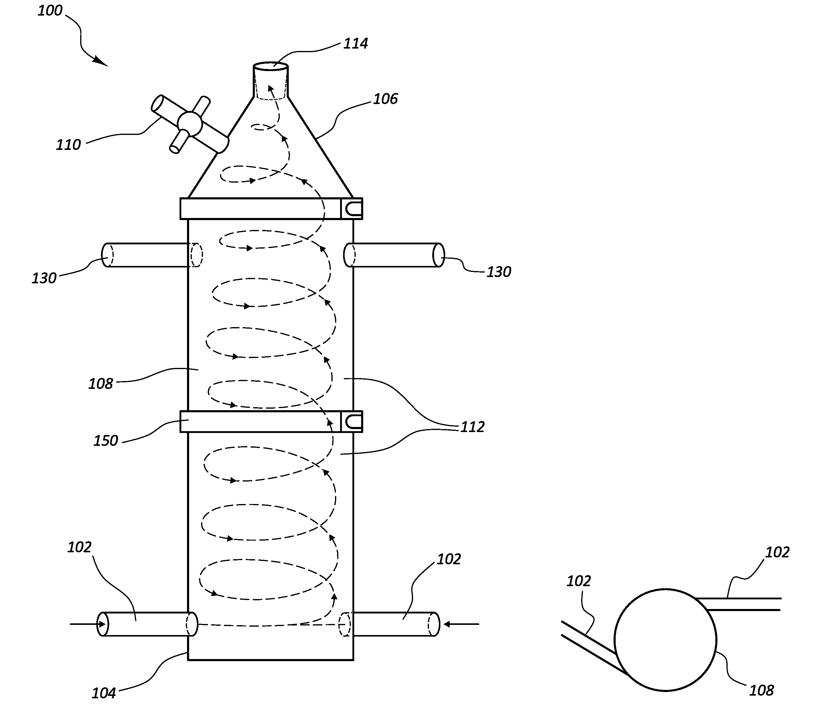
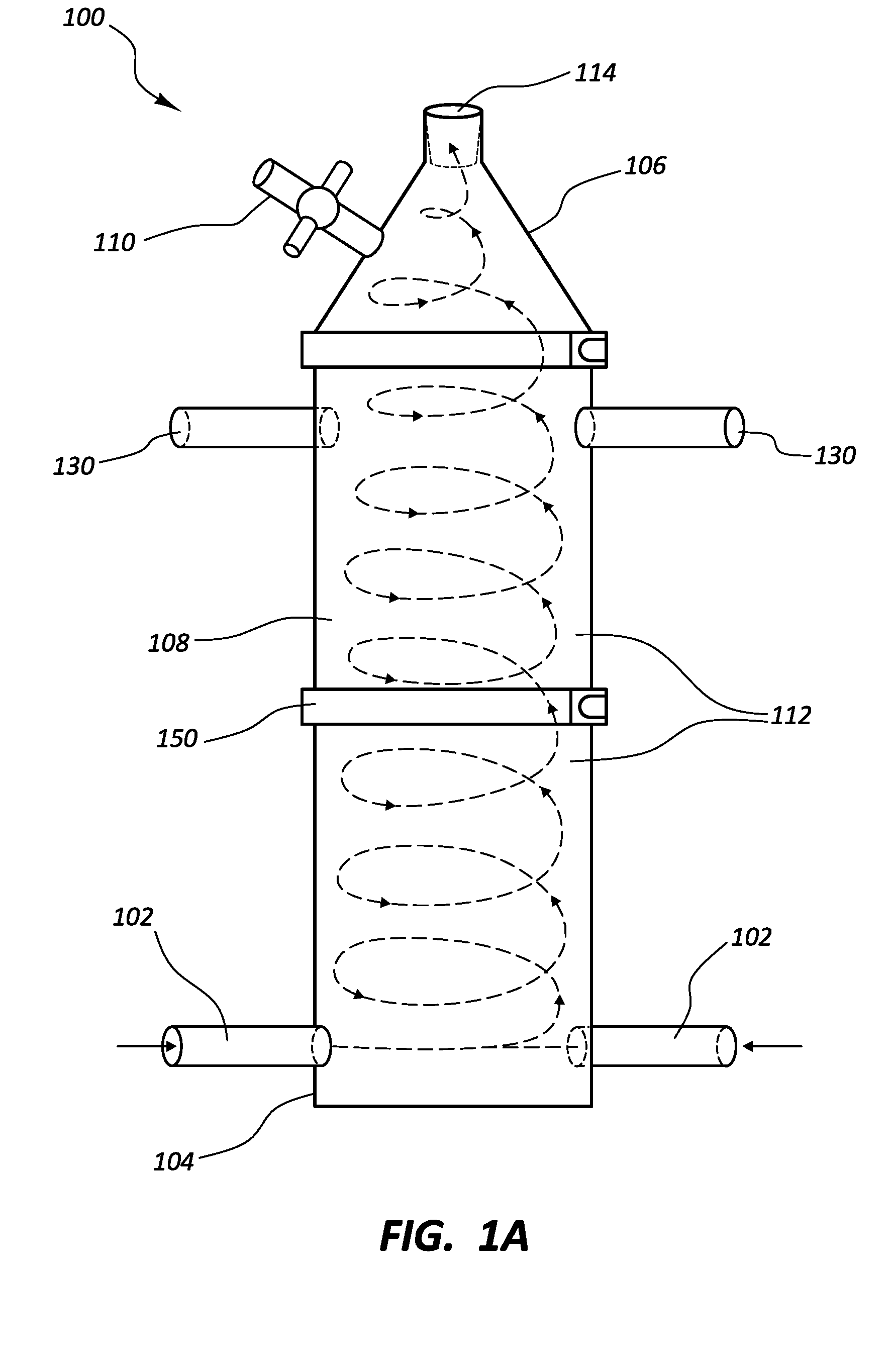
[0034]The present disclosure relates to systems, devices, and methods for processing one or more fluids by passing the one or more fluids through a vortex reactor in order to impart physical and / or chemical effects to the one or more fluids.

[0035]Some vortex reactor embodiments include a reactor body having a first end and a second end, one or more inlet ports, and one or more outlets, wherein the inlet port(s) and the outlet(s) is / are arranged to enable formation of at least one vortex within the reactor body as reactor fluid is passed into the vortex reactor. As explained in greater detail below, some embodiments are configured to generate a single vortex, and some embodiments are configured to generate multiple (e.g., dual) vortices. In addition, some embodiments include a vortex inducer configured to induce the formation of one or more vortices within the reactor and / or to augment or otherwise adjust the fluid dynamics of the one or more vortices.

[0036]One or more...


PUM

PropertyMeasurementUnit
Frequencyaaaaaaaaaa
Frequencyaaaaaaaaaa
Frequencyaaaaaaaaaa

Abstract

A vortex reactor includes a reactor body having first and second ends, with one or more inlet ports coupled to the first end. The reactor is configured to form one or more vortices in a fluid passed into the reactor. The inlet port(s) may be positioned to advance a reactor fluid into the reactor body at an angle tangential to an inner surface of the reactor body, forming a vortex that advances toward the second end along the inner surface of the reactor body. A vortex induction mechanism can be disposed within the reactor to induce or augment a vortex within the reactor. The reactor includes an ultrasound-imparting device configured to generate cavitation bubbles in the reactor fluid. The fluid flow within the reactor concentrates the cavitation bubbles within the vortex, thereby providing beneficial physical and/or chemical effects, while protecting the reactor walls and other reactor components from cavitational erosion.

Description

CROSS-REFERENCE TO RELATED APPLICATIONS[0001]This application claims the benefit of U.S. Provisional Patent Application No. 62 / 169,345, filed on Jun. 1, 2015, U.S. Provisional Patent Application No. 62 / 180,973, filed on Jun. 17, 2015, U.S. Provisional Patent Application No. 62 / 189,378, filed on Jul. 7, 2015, U.S. Provisional Patent Application No. 62 / 192,214, filed on Jul. 14, 2015, U.S. Provisional Patent Application No. 62 / 218,390, filed on Sep. 14, 2015, and U.S. Provisional Patent Application No. 62 / 271,216, filed on Dec. 22, 2015, the disclosures of which are incorporated herein in their entirety.BACKGROUND[0002]The present disclosure relates generally to the processing of one or more fluids by passing the one or more fluids through a reactor. In particular, the present disclosure relates to systems, devices, and methods for processing one or more fluids by passing the one or more fluids through a vortex reactor in order to impart physical and / or chemical effects to the one or ...

Claims


Application Information

Patent Timeline
IPC IPC(8): B01J19/28B04C5/08C01B3/02C02F1/38C02F1/46C10G31/10B01F5/00B01D21/26
CPCB01J19/28B01F5/0057B04C5/08B01D21/265C02F1/38B01J2219/0877C10G31/10C01B3/02C02F2101/30C02F2103/08B01J2219/0803C02F1/4604B01J19/2405B01J2219/00772B01J19/241C02F1/36C02F1/40C02F1/441C02F11/00C02F2101/32C02F2301/024C02F2301/026C01B3/06C01B15/027C10G31/06Y02E60/36B01F25/1042B01F25/10B01F25/43141B01F25/431972B01F31/841
Inventor KRESS, DON EDWARDYUSOF, KAMALUL ARIFIN
Owner CETAMAX VENTURES
Why Eureka
Try Eureka