Egr system with particle filter and wastegate

a technology of wastegate and particle filter, which is applied in the direction of engine components, air cleaners for fuel, internal combustion piston engines, etc., can solve the problems of too low oxygen content in the exhaust gas to completely burn off the particulate matter contained in the filter, and achieve the effect of improving the regeneration of the particulate filter and significantly improving the emission of pollutan

Active Publication Date: 2016-12-01
TENNECO GMBH
View PDF25 Cites 32 Cited by
  • Summary
  • Abstract
  • Description
  • Claims
  • Application Information

AI Technical Summary

Benefits of technology

[0012]Cooling of the recirculated exhaust gas is advantageous for optimizing the combustion with EGR systems for gasoline engines, since a recirculation of uncooled exhaust gases, particularly at higher loads and at full load, results in higher suction temperatures as a result of the hot exhaust gases supplied. This, in turn, results in filling losses and an increase in the knocking tendency of the gasoline engine. These are accompanied by undesirable losses in performance of the engine. These disadvantages can be reduced by cooling the recirculated exhaust gas. However, this results in the production of an increased amount of condensates—consisting of water and / or hydrocarbons and hydrocarbon compounds respectively and incompletely burnt combustion residues—in the recirculated exhaust gas, resulting in a higher degree of sootiness in the form of wet adhesive deposits in the EGR system as well as in the air-intake system. A combination of the particulate filter with the charge-air cooler, as described for a diesel particulate filter in accordance with EP 2 194 351 B1, cannot therefore be considered, in order to avoid a risk of clogging due to the deposits described above in the particulate filter.
[0045]To this end, it can be advantageous if on introducing secondary air through the device a) the EGR valve is opened and, optionally, exhaust gas is additionally conducted through the bypass conduit, wherein the bypass throttle valve is at least partially open or b) the EGR valve is closed and, alternatively, exhaust gas is conducted through the bypass conduit, wherein the bypass throttle valve is at least partially open. The mass stream additionally introduced can be carried away via the bypass conduit or the EGR conduit. In the latter case, an improved regeneration of the particulate filter is guaranteed.

Problems solved by technology

Since the vast majority of gasoline engines are operated stoichiometrically, the oxygen content in the exhaust gas can be too low to completely burn off the particulate matter contained in the filter.

Method used


Image

  • Egr system with particle filter and wastegate
  • Egr system with particle filter and wastegate
  • Egr system with particle filter and wastegate

Examples


Embodiment Construction

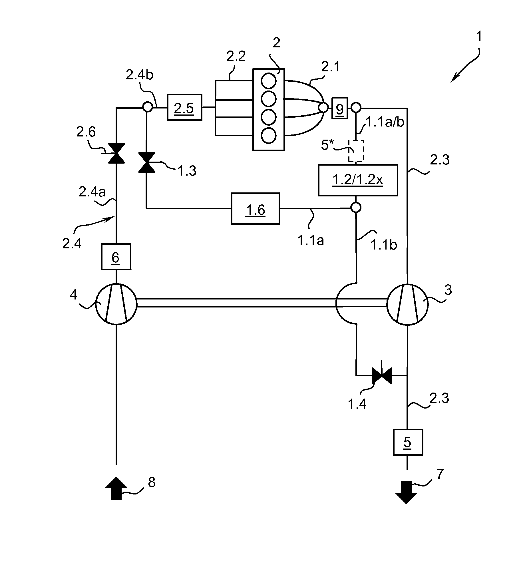
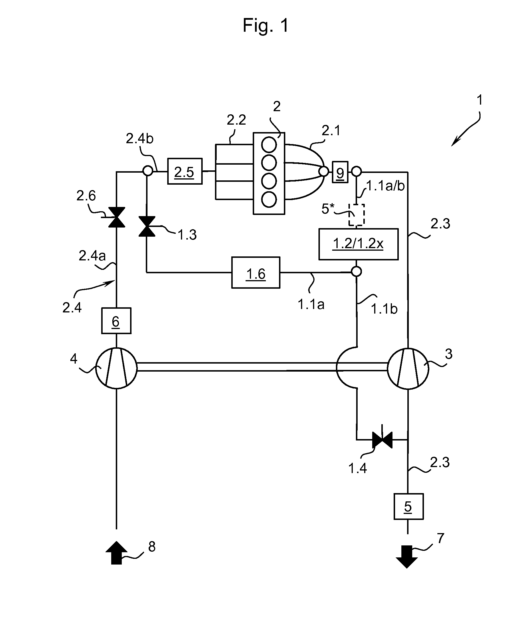
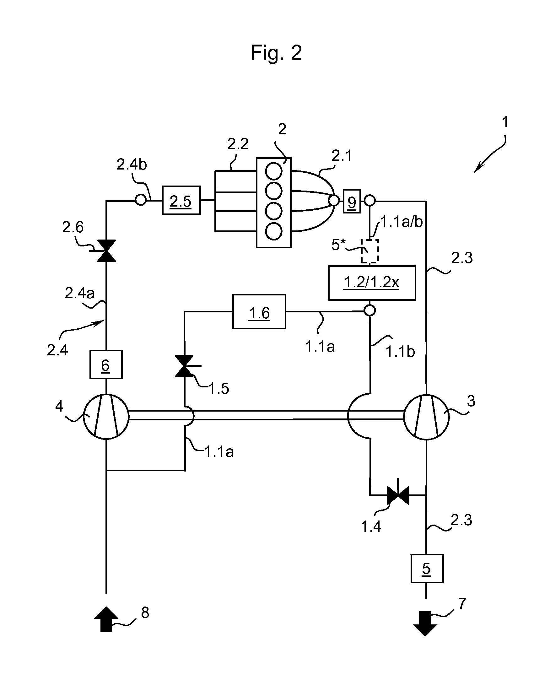
[0050]All of the schematic diagrams according to FIGS. 1-3 show an emissions control system 1 (EGR system) which is integrated into the exhaust gas and charge-air system of a gasoline engine 2 having an exhaust manifold 2.1 and an inlet manifold 2.2 as well as having an exhaust gas turbine 3 and a charge-air compressor 4. The exhaust and charge-air system has an exhaust gas conduit 2.3 which is connected to the exhaust manifold 2.1 of the gasoline engine 2, into which exhaust gas conduit the turbine 3 is integrated. At the end of the exhaust gas conduit 2.3, exhaust gas 7 leaves the emissions control system 1 and flows into the other exhaust line which is not shown. In addition, an inlet conduit 2.4 connected to the intake manifold 2.2 of the gasoline engine 2 is provided, into which the compressor 4 is integrated. The inlet conduit 2.4 is supplied with fresh air 8 by means of an air supply system which is not shown. In addition, at least one exhaust gas recirculation conduit (EGR c...


PUM


Abstract

An emissions control system for a gasoline engine having an exhaust gas conduit which can be connected to an exhaust manifold of the gasoline engine, having an inlet conduit which can be connected to an inlet manifold of the gasoline engine and having a turbine arranged in the exhaust gas conduit. At least one exhaust gas recirculation conduit is provided, which opens into the inlet conduit, and the exhaust gas conduit has at least one bypass conduit, which opens into the exhaust gas conduit downstream of the turbine, wherein a) the exhaust gas recirculation conduit branches off upstream of the turbine and the bypass conduit branches off at the exhaust gas recirculation conduit or b) the bypass conduit branches off upstream of the turbine and the exhaust gas recirculation conduit branches off at the bypass conduit, wherein c) at least one particulate filter, is arranged in the exhaust gas recirculation conduit or in the bypass conduit upstream of the exhaust gas recirculation conduit or in the exhaust gas conduit upstream of the exhaust gas recirculation conduit.

Description

FIELD OF THE INVENTION[0001]The invention relates to an emissions control system for a gasoline engine having an exhaust gas conduit which can be connected to an exhaust manifold of the gasoline engine, having an inlet conduit which can be connected to an inlet manifold of the gasoline engine and having a turbine arranged in the exhaust gas conduit.BACKGROUND OF THE INVENTION[0002]An exhaust gas recirculation system for diesel engines is known from U.S. Pat. No. 5,671,600 A. A particulate filter, to which an exhaust gas recirculation conduit is connected, is provided at the exhaust gas outlet and / or at the exhaust gas conduit. Upstream of a charge-air compressor the exhaust gas recirculation conduit opens into the intake conduit. A valve for modifying the exhaust gas mass stream is provided inside the exhaust gas recirculation conduit. The particulate filter is used to protect the charge-air compressor and / or the charge-air cooler against pollution.[0003]A particulate filter in the ...

Claims


Application Information

Patent Timeline
Patent Type & Authority Applications(United States)
IPC IPC(8): F02M26/04F02M35/02
CPCF02M35/02F02M26/04F02B37/18F02M26/05F02M26/06F02M26/07F02M26/22F02M26/35F02M26/44Y02T10/12
Inventor FISCHER, MICHAEL
Owner TENNECO GMBH
Why Eureka
Try Eureka