Microbial fuel cell, microbial fuel cell system, and method for using microbial fuel cell

a fuel cell and microbial technology, applied in the field of microbial fuel cells, can solve the problems of imbalance between the performance of the negative electrode and the positive electrode, the inability to recognize the problem derived from the imbalance, and the insufficient enhancement of the electrochemical reaction efficiency. , to achieve the effect of significantly high electrochemical reaction efficiency and insufficient enhancement of the electrochemical reaction efficiency

Inactive Publication Date: 2016-12-01
PANASONIC CORP
View PDF3 Cites 3 Cited by
  • Summary
  • Abstract
  • Description
  • Claims
  • Application Information

AI Technical Summary

Benefits of technology

[0005]As described in Patent Literature 1, when a positive electrode is a porous gas diffusion electrode, electrochemical reaction efficiency is significantly high in the positive electrode. However, the electrochemical reaction efficiency is not sufficiently enhanced in a negative electrode compared with that in the positive electrode because the electrochemical reaction in the negative electrode involves microorganisms. This results in a performance imbalance between the negative electrode and the positive electrode that is the gas diffusion electrode.

Problems solved by technology

However, the electrochemical reaction efficiency is not sufficiently enhanced in a negative electrode compared with that in the positive electrode because the electrochemical reaction in the negative electrode involves microorganisms.
This results in a performance imbalance between the negative electrode and the positive electrode that is the gas diffusion electrode.
Since the conventional microbial fuel cells have not been focused on a performance imbalance between the electrodes, problems derived from the imbalance have not been recognized.
However, the performance imbalance between the electrodes shows that materials of one electrode having higher performance are excessive, which should be solved in view of conservation of recourses.

Method used


Image

  • Microbial fuel cell, microbial fuel cell system, and method for using microbial fuel cell
  • Microbial fuel cell, microbial fuel cell system, and method for using microbial fuel cell
  • Microbial fuel cell, microbial fuel cell system, and method for using microbial fuel cell

Examples


first embodiment

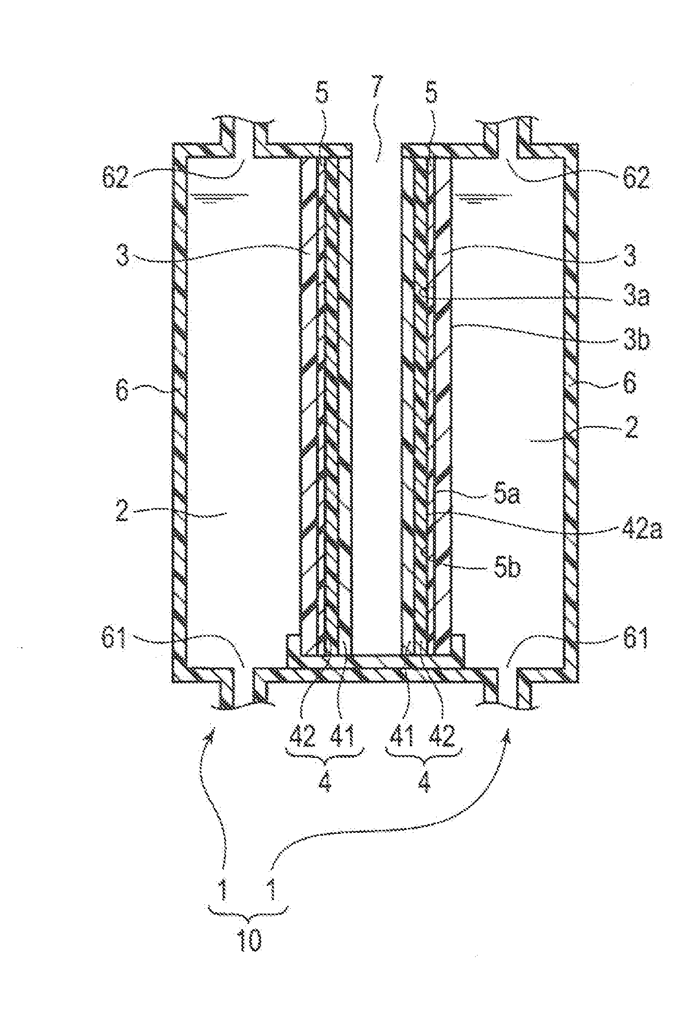
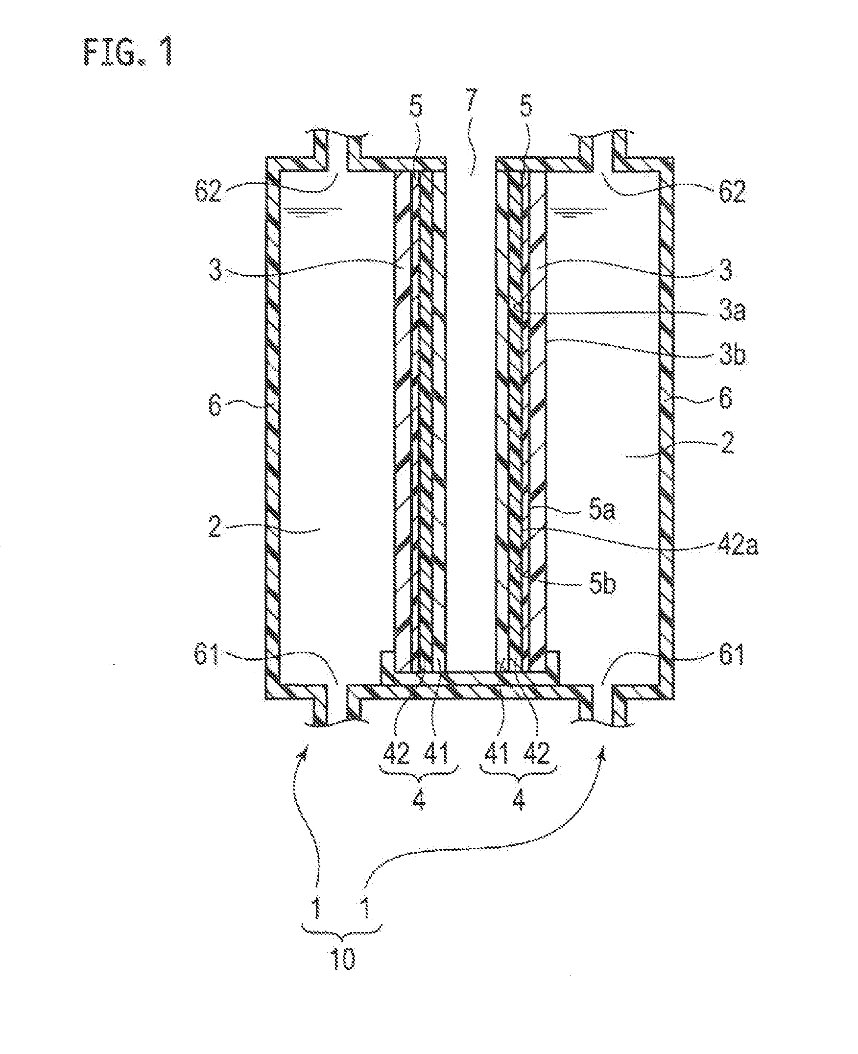
[0018]As shown in FIG. 1, a microbial fuel cell 1 according to the present embodiment includes an electrolysis solution 2, a negative electrode 3, a positive electrode 4, and a separating membrane 5. The electrolysis solution 2 includes organic matter. The negative electrode 3 holds anaerobic microorganisms and is in contact with the electrolysis solution 2. The positive electrode 4 is a gas diffusion electrode including a water-repellent layer 41 and a gas diffusion layer 42 placed on the water-repellent layer 41.

[0019]A ratio of the area of the negative electrode 3 in a direction vertical to the stacking direction of the negative electrode 3, the positive electrode 4, and the separating membrane 5 (in a plane direction) to the area of the gas diffusion layer 42 in the plane direction ([area of negative electrode] / [area of gas diffusion layer]), is defined as T1. A ratio of a maximum current density of the positive electrode 4 at an electric potential of the positive electrode 4 in...

second embodiment

[0077]A microbial fuel cell 1A and a microbial fuel cell system 10A according to a second embodiment will be described below with reference to the drawings. The same elements as those in the first embodiment are designated by the same reference numerals in this embodiment, and overlapping explanations are not repeated below.

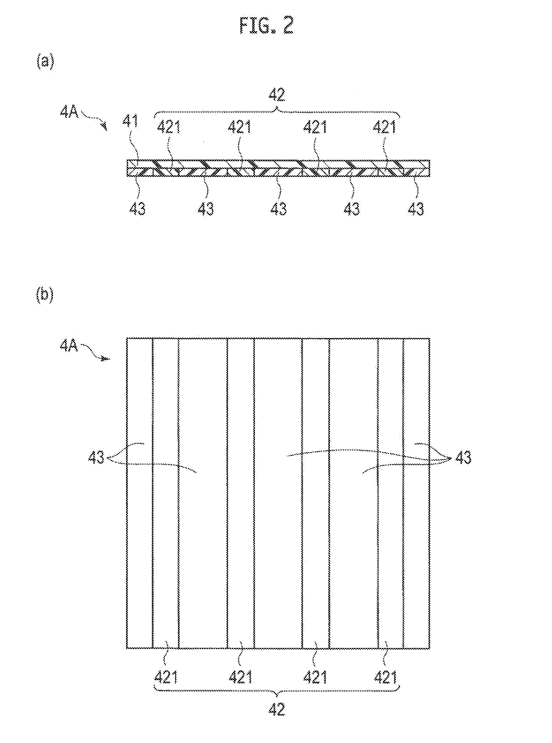
[0078]The microbial fuel cell 1A according to the present embodiment is required to satisfy the relationship of T1 and T2 represented by the expression (1), as in the case of the first embodiment. A positive electrode 4B of the present embodiment preferably has a configuration in which the gas diffusion layer 42 is partly placed on the water-repellent layer 41, as in the case of the positive electrode 4A described above.

[0079]As shown in FIG. 3, the gas diffusion layer 42 of the present embodiment is preferably partly provided and located on the upper side of the positive electrode 4B. In particular, the gas diffusion layer 42 partly stacked on the water-repellen...


PUM

PropertyMeasurementUnit
current densityaaaaaaaaaa
electric potentialaaaaaaaaaa
electrical conductiveaaaaaaaaaa

Abstract

A microbial fuel cell (1) includes an electrolysis solution (2) including organic matter, a negative electrode (3) holding anaerobic microorganisms and being in contact with the electrolysis solution, and a positive electrode (4) including a water-repellent layer (41) and a gas diffusion layer (42) placed on the water-repellent layer. A ratio of an area of the negative electrode to an area of the gas diffusion layer is defined as T1, and a ratio of a maximum current density of the positive electrode at an electric potential of the positive electrode in an electrode system including the electrolysis solution, the negative electrode, and the positive electrode to a maximum current density of the negative electrode at an electric potential of the negative electrode in the electrode system is defined as T2. The ratios T1 and T2 satisfy the relationship of the expression (1): T21/2≦T1≦T22.

Description

TECHNICAL FIELD[0001]The present invention relates to a microbial fuel cell, a microbial fuel cell system, and a method for using a microbial fuel cell.BACKGROUND ART[0002]Microbial fuel cells convert chemical energy of organic matter contained in wastewater into electrical energy through a catalytic reaction of microorganisms (metabolism, biochemical conversion), and oxidize and reduce the organic matter. Such microbial fuel cells produce the electrical energy directly from the organic matter by the action of microorganisms. The microbial fuel cells are therefore expected to improve energy recovery efficiency compared with conventional energy recovery systems that go through a process of converting organic matter into biogas for energy recovery. Such microbial fuel cells are utilized not only for power generation but also for wastewater treatment, organic waste treatment, and incidental facilities for organic waste treatment.[0003]A microbial fuel cell includes a negative electrode...

Claims


Application Information

Patent Timeline
Patent Type & Authority Applications(United States)
IPC IPC(8): H01M8/16H01M4/90H01M4/86
CPCH01M8/16H01M4/90H01M4/8605H01M4/96H01M8/0239Y02E60/50
Inventor SUZUKI, YUYAUSUI, HIROAKI
Owner PANASONIC CORP
Why Eureka
Try Eureka