Monolithic tunable terahertz radiation source using nonlinear frequency mixing in quantum cascade lasers

a quantum cascade laser and radiation source technology, applied in semiconductor lasers, optics, instruments, etc., can solve the problems of not being able to design monolithic thz dfg-qcl tuners, having moving parts, and bulky external cavity tunable laser systems

Inactive Publication Date: 2016-12-01
BOARD OF RGT THE UNIV OF TEXAS SYST
View PDF15 Cites 13 Cited by
  • Summary
  • Abstract
  • Description
  • Claims
  • Application Information

AI Technical Summary

Benefits of technology

[0009]In one embodiment of the present invention, a terahertz difference-frequency generation quantum cascade laser source comprises a quantum cascade laser comprising a substrate. The quantum cascade laser further comprises a lower cladding semiconducting layer positioned above the substrate. The quantum cascade laser additionally comprises an active region layer with optical nonlinearity, where the active region layer is positioned on the lower cladding semiconductor layer, and where the active region layer is arranged as a multiple quantum well structure with optical nonlinearity for terahertz generation. Furthermore, the quantum cascade laser comprises an upper cladding semiconducting layer positioned on the active region layer. Additionally, the quantum cascade laser comprises two or more mid-infrared feedback gratings etched into spatially separated sections of the lower or upper cladding semiconducting layers, where the two or more mid-infrared feedback gra

Problems solved by technology

However, external cavity tunable laser systems are bulky, have moving parts, and require precise alignment of optical components.
Hence, there is

Method used


Image

  • Monolithic tunable terahertz radiation source using nonlinear frequency mixing in quantum cascade lasers
  • Monolithic tunable terahertz radiation source using nonlinear frequency mixing in quantum cascade lasers
  • Monolithic tunable terahertz radiation source using nonlinear frequency mixing in quantum cascade lasers

Examples


Embodiment Construction

[0024]In the following description, various embodiments are described. For purposes of explanation, specific configurations and details are set forth in order to provide a thorough understanding of the embodiments. Well-known features may be omitted or simplified in order not to obscure the embodiment being described.

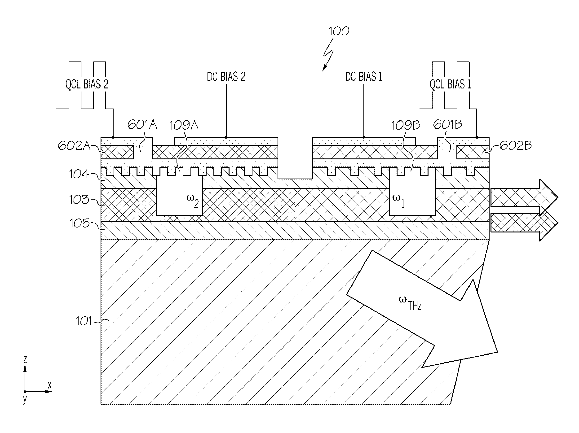
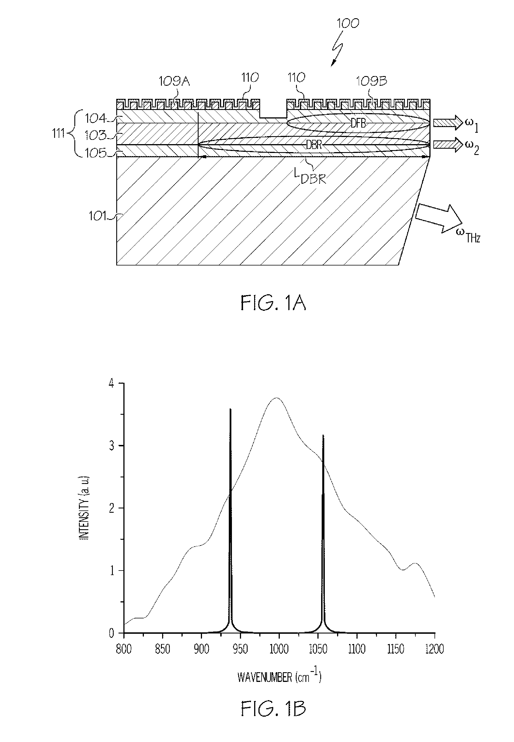
[0025]THz tuning in the difference-frequency generation (DFG) process ωTHz=ω1−ω2, where ω1>ω2, can be achieved by changing mid-infrared (mid-IR) pump frequencies, ω1 or ω2. Since a small fractional shift in mid-IR pump frequency translates into a large fractional change of THz emission frequency, this approach leads to monolithic THz semiconductor sources with an extremely wide tuning range as discussed further below. To independently control two mid-IR pump frequencies, the device of the present invention includes two independently-biased distributed grating sections for each mid-infrared pump wavelength. By controlling the DC current through these sections, one can el...


PUM


Abstract

A terahertz difference-frequency generation quantum cascade laser source that provides monolithic, electrically-controlled tunable terahertz emission. The quantum cascade laser includes a substrate, a lower cladding layer positioned above the substrate and an active region layer with optical nonlinearity positioned on the lower cladding layer. The active region layer is arranged as a multiple quantum well structure. One or more feedback gratings are etched into spatially separated sections of the cladding layer positioned on either side of the active region. The periodicity of each grating section determines the mid-infrared lasing frequencies. The grating sections are electrically isolated from one another and biased independently. Tuning is achieved by changing a refractive index of one or all of the grating sections via a DC current bias thereby causing a shift in the mid-infrared lasing frequency. In this manner, a monolithic, electrically-pumped, tunable THz source is achieved.

Description

RELATED APPLICATIONS[0001]This application claims priority, under 35 U.S.C. 371, to International patent application PCT / US15 / 14371, “Method and Apparatus for a Monolithic Tunable Terahertz Radiation Source Using Nonlinear Frequency Mixing in Quantum Cascade Lasers,” filed Feb. 4, 2015, which claims priority to,[0002]U.S. Provisional Patent Application Ser. No. 61 / 935,400, “Method and Apparatus for a Monolithic Tunable Terahertz Radiation Source Using Nonlinear Frequency Mixing in Quantum Cascade Lasers,” filed Feb. 4, 2014,[0003]Both of which are incorporated by reference herein in their entirety.GOVERNMENT INTERESTS[0004]This invention was made with government support under Grant nos. ECCS1150449 and ECCS0925217 awarded by the National Science Foundation and Grant no. N66001-12-1-4241 awarded by the Space and Naval Warfare Systems Center (SSC) Pacific. The government has certain rights in the invention.BACKGROUND[0005]The present invention relates generally to tunable terahertz qu...

Claims


Application Information

Patent Timeline
IPC IPC(8): H01S5/06G02F1/35H01S5/0625H01S5/34H01S5/343H01S5/12
CPCH01S5/0604H01S5/3401G02F2203/13H01S5/06258G02F1/3534H01S5/34306H01S5/0207H01S5/0422H01S5/06256H01S5/1021H01S5/1092H01S5/12H01S5/125H01S5/0208
Inventor BELKIN, MIKHAILJUNG, SEUNGYONGVIJAYRAGHAVAN, KARUN
Owner BOARD OF RGT THE UNIV OF TEXAS SYST
Why Eureka
Try Eureka