
Prismatic pressure tank having lattice structure

a pressure tank and lattice technology, applied in the field of pressure tanks, can solve the problems of not being able to meet significant internal pressure, not being able to make very large membrane shells, and more than double the amount of material required, so as to achieve efficient use of surrounding space, high volume efficiency, and the effect of extending the size of the pressure tank

Active Publication Date: 2016-12-08
KOREA ADVANCED INST OF SCI & TECH
View PDF5 Cites 3 Cited by
  • Summary
  • Abstract
  • Description
  • Claims
  • Application Information

AI Technical Summary

Benefits of technology

[0014]An object of the present invention is to provide a new type of high-pressure tank having a mainly rectangular, prismatic shape, that is, a pressure tank with a very high volume efficiency and at the same time be capable of enduring high pressure of a fluid and change in temperature while enabling to make the tank of any size by modular extension in any of the three spatial directions.
[0015]Further, another object of the present invention is to provide a pressure tank including high volume efficiency and preventing a fluid in the pressure tank from being leaked by allowing for integration of a secondary barrier.
[0016]Another object of the invention is to provide a tank that is suitable for allowing any level of fluid filling and being able to withstand very large dynamic motions of the tank by way of effective fluid damping from the internal load carrying structure and by having strong tank walls that can sustain dynamic fluid pressures from sloshing.

Problems solved by technology

This implies that membrane type shells cannot be made very big when the internal design pressure is large.
Another aspect with such pressure vessels is that such tanks cannot be made as a complete double barrier tank without having one complete tank within another complete tank, thereby more than doubling the amount of material required.
Such tanks are not suited significant internal pressure and normally operate at atmospheric pressure.
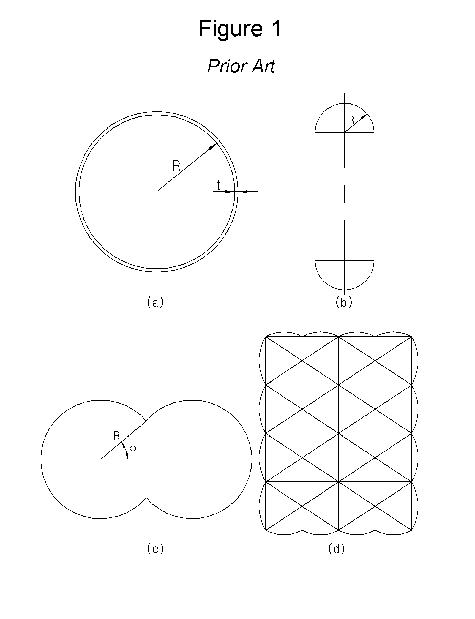
As seen from the table the spherical tanks have the best material performance; unfortunately, their volume efficiency is very poor.
This means that it is not possible to utilize a high portion of a given outer, surrounding volume for actual storage within a series of spherical tanks.
However, since the lobe type tank is manufactured by intersecting circular tank with each other as well as with cylindrical and planar tank walls, it is difficult to manufacturing such type of tank.
High stresses will typically be concentrated at the intersecting lines between internal bulkhead, cylindrical parts and doubly curved parts, which may greatly reduce the material efficiency of such tanks.
In practice it is not possible to make a high pressure lobe tank as a double barrier tank because of geometrical complexity.
A main drawback with cellular tanks is that it is difficult to design good ways of closing the ends of the cells without creating significant local bending deformations and stress concentrations.
Further, there is a problem in that it is difficult to form the outer wall of the cellular type tank as a double wall in connection with a design.

Method used


Image

  • Prismatic pressure tank having lattice structure
  • Prismatic pressure tank having lattice structure
  • Prismatic pressure tank having lattice structure

Examples


Embodiment Construction

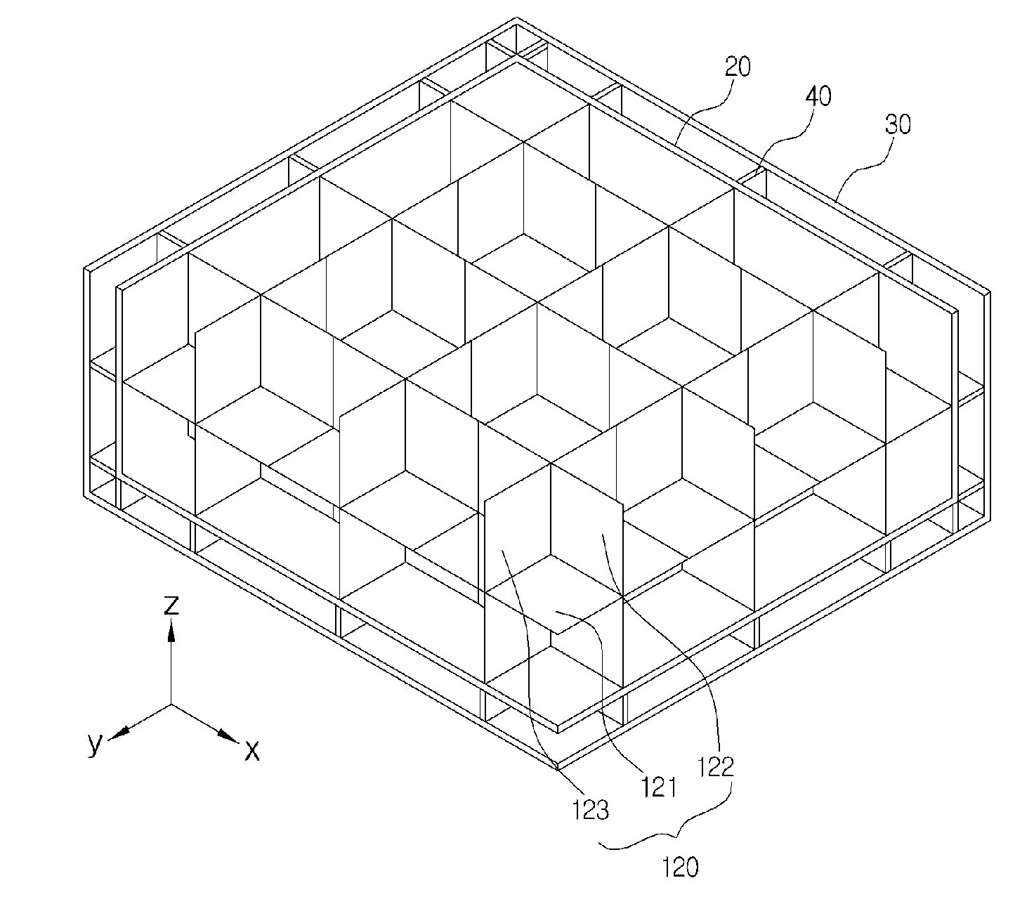
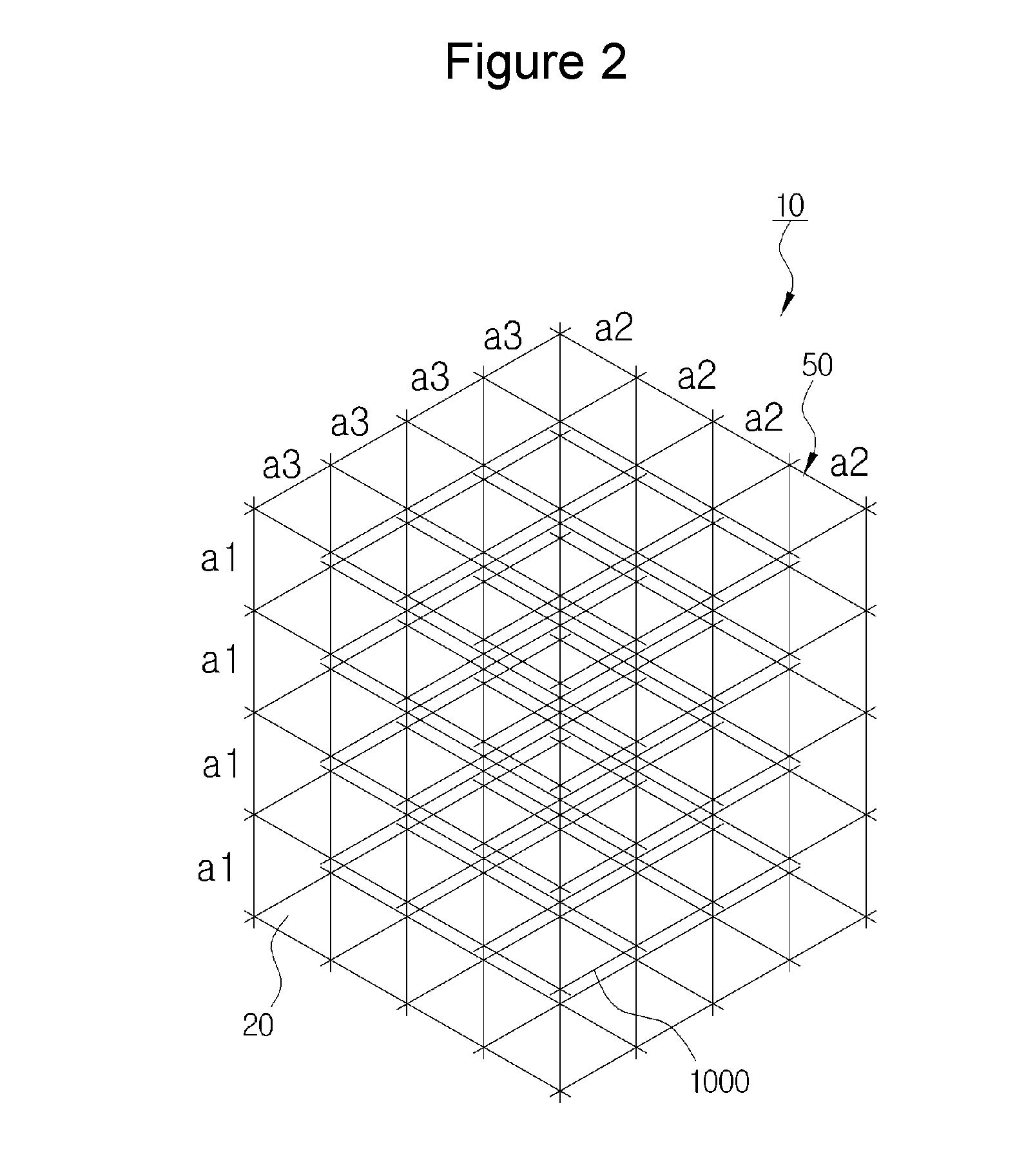
[0075]10: Pressure tank20: Inner wall

[0076]21: wall stiffening member

[0077]22: beam-wall bracket

[0078]23: surface stiffening member

[0079]24: beam-beam bracket

[0080]30: Outer wall

[0081]40: Girder4l: Flange

[0082]50: Tank body

[0083]51: Tank body with corners chamfered straight.

[0084]52: Tank body with corners chamfered curvedly.

[0085]1000: Cell structure having load-carrying internal lattice structure

[0086]100: Surface lattice structure

[0087]110: Surface lattice unit

[0088]114: Intersecting part

[0089]120: Cell wall

[0090]121: First cell wall122: Second cell wall

[0091]123: Third cell wall

[0092]200: Beam structure210: Beam lattice unit

[0093]211: X-axis beam structure212: Y-axis beam structure

[0094]213: Z-axis beam structure214: Intersecting part

[0095]220: Quadrangular beam structure

[0096]230: Circular beam structure

[0097]231: Circular X-axis beam structure

[0098]232: Circular Y-axis beam structure

[0099]233: Circular Z-axis beam structure

[0100]240: Combined beam structure

[0101]241: Combined ...


PUM


Abstract

Provided is a pressure tank having a lattice structure, including: a tank body that has a high-pressure fluid accommodated therein and is manufactured to have a prismatic shape; and cell structures that are disposed in the prismatic tank body, are manufactured in a lattice form, arrive from one side wall of the tank body to the other side wall thereof facing it, and are orthogonally arranged regularly.

Description

CROSS-REFERENCE TO RELATED APPLICATIONS[0001]This application is a divisional application of U.S. Ser. No. 14 / 110,580, filed on Oct. 8, 2013, which is a national entry of PCT Application No. PCT / KR2012 / 003157 filed on Apr. 25, 2012, which claims priority to and the benefit of Korean Application No. 10-2011-0038676 filed on Apr. 25, 2011, Korean Application No. 10-2 01 1-0038678 filed on Apr. 25, 2011 and Korean Application No. 10-2011-0038681 filed on Apr. 25, 2011, in the Korean Patent Office, the entire contents of which are incorporated herein by reference.TECHNICAL FIELD[0002]The present invention relates to a pressure tank, and particularly, to a pressure tank having a lattice type internal load carrying structure, in which the pressure tank is manufactured in mainly a hexahedral shape and where the enclosing tank walls are reinforced for lateral pressure by way of stiffening members consistent with the lattice structure to withstand pressure by internal fluid and is manufactur...

Claims


Application Information

Patent Timeline
Patent Type & Authority Applications(United States)
IPC IPC(8): F17C1/08F17C1/12F17C13/02
CPCF17C1/08F17C13/02F17C1/12F17C2201/0161F17C2270/0105F17C2203/0304F17C2221/033F17C2250/04F17C2260/011F17C2203/013F17C3/025F17C2201/0157F17C2201/0166F17C2201/0171F17C2201/052F17C2203/0345F17C2203/0629F17C2209/221F17C2223/0161F17C2223/033F17C2223/035F17C2250/0452F17C2250/0491F17C2260/016F17C1/02
Inventor CHANG, DAE JUNBERGAN, PAL, G
Owner KOREA ADVANCED INST OF SCI & TECH
Learn More