3-d printer in polar coordinates
- Summary
- Abstract
- Description
- Claims
- Application Information
AI Technical Summary
Benefits of technology
Problems solved by technology
Method used
Image

Examples
embodiment 1
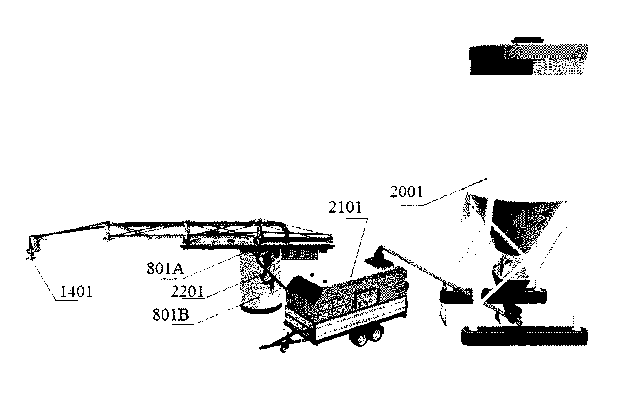
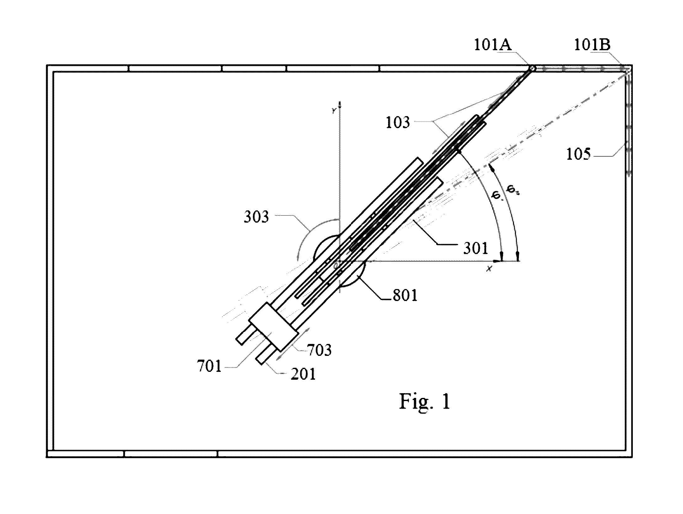
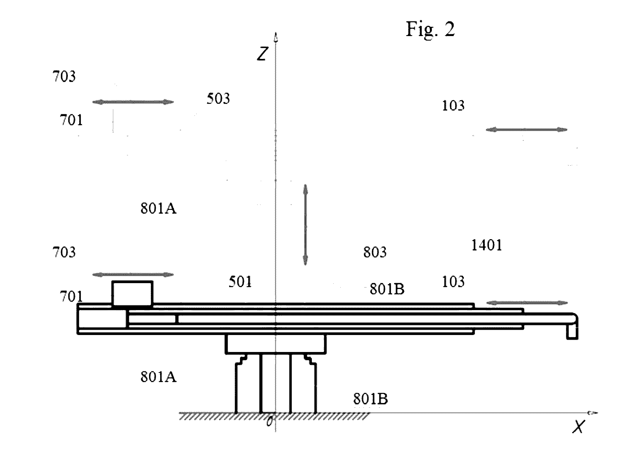
[0044]Referring to FIG. 1 and FIG. 2, in addition to the translational 103 and rotational 303 motion in the XOY plane, the device carries out translational motions 803 along the Z axis during the printing process, as a result of which the extruder 1401 can be raised and lowered, taking up positions at 501 or 503, respectively. The height of the extruder 1401 is determined in the XOZ plane by its applicate (its coordinate on the Z axis), or by the distance from it to the XOY plane in space.
[0045]In a preferred embodiment the design allows printing a construction, encompassing the surroundings out to a radius of 20 meters, with center at the point where coordinates start. In alternative embodiments the radius is greater than 20 meters.
[0046]In this embodiment the rotation mechanism 801A is located between extendable boom arm 201 with telescoping extendable sections 301 with extruder 1401 and telescoping-type lift mechanism 801B, so that during printing process only the extendable boom...
embodiment 2
[0054]Referring to FIG. 3 and FIG. 4, in addition to the translational 103 and rotational 303 motion in the X and V plane, the device carries out translational motions 803 along the Z axis during the printing, process, as a result of which the extruder 1401 can be raised and lowered, taking up positions at 501 or 503, respectively. The height of the extruder 1401 is determined in the XOZ plane by its applicate (its coordinate on the Z axis), or by the distance from it to the XOY plane in space. In a preferred embodiment the design allows printing a construction, encompassing the surroundings out to a radius of 20 meters, with center at the point where coordinates start In alternative embodiments the radius is greater than 20 meters.
[0055]The rotation mechanism 801A is located in the base of the whole construction, the 3D printer, wherein during the printing process, the extendable boom arm 201 with telescoping extendable sections 301 and all nodes connected to it (counterweight mech...
embodiment 3
[0067]Operation of the 3D printer is carried out according to the following method: Step 1: providing a given design schematic for the building or structure set out in an XYZ coordinate system with an X axis, Y axis, and Z axis. Step 2: placing: a 3D printer unit at coordinates 0, 0, 0. Step 3: the 3D printer unit having an extendable boom arm with an extruder at one end and a counterweight mechanism at an opposite end of the extruder. Step 4: the counterweight mechanism moving to maintain center of mass along Z axis at X,Y coordinate 0,0 while the extendable boom arm is extending or contracting, Step 5: the extendable boom arm undergoing translational and rotational motion to change a position of the extruder in an XOY plane of the XYZ coordinate system. Step 6: the extendable boom arm lifting and lowering to change a position of the extruder in an XOZ plane of the XYZ coordinate system. Step 7: pumping a concrete-based chemical solution through the 3D printer to the extruder at a ...
PUM
| Property | Measurement | Unit |
|---|---|---|
| Pressure | aaaaa | aaaaa |
| Radius | aaaaa | aaaaa |
| Flow rate | aaaaa | aaaaa |
Abstract
Description
Claims
Application Information
 - Generate Ideas
- Intellectual Property
- Life Sciences
- Materials
- Tech Scout
- Unparalleled Data Quality
- Higher Quality Content
- 60% Fewer Hallucinations
Browse by: Latest US Patents, China's latest patents, Technical Efficacy Thesaurus, Application Domain, Technology Topic, Popular Technical Reports.
© 2025 PatSnap. All rights reserved.Legal|Privacy policy|Modern Slavery Act Transparency Statement|Sitemap|About US| Contact US: help@patsnap.com