Method of modifying substrate surface

a technology of surface modification and pdms, which is applied in the field of surface modification, can solve the problems of not being able to apply pdms in solid phase to biomedical devices, complicated and time-consuming steps of some modification processes, and costing a great fortune, and achieves enhanced hydrophilicity of the modified pdms surface, elasticity and flexibility, and enhanced hydrophilicity.

Active Publication Date: 2016-12-15
NATIONAL TSING HUA UNIVERSITY
View PDF5 Cites 3 Cited by
  • Summary
  • Abstract
  • Description
  • Claims
  • Application Information

AI Technical Summary

Benefits of technology

[0009]For aforementioned problems in the prior art, the purpose of present invention is to provide a method of modifying surface with low cost and be suitable for massive production, while the modified surface is provided with stable hydrophilicity. Therefore, the aforementioned problems regarding surface modification in the prior art may be solved.
[0020]In summary, the O2 plasma treatment and the UV curing coating are combined in the present invention for the first time, making the UV curing coating to form a thin film effectively on the O2 plasma-treated surface and the modified surface of PDMS to be hydrophilic. According to the method of modifying the substrate surface, the present invention may have one or more following advantages:
[0021](1) The surface hydrophilicity of the modified PDMS surface may be greatly enhanced by combining the O2 plasma treatment step and the UV curing coating step according to an embodiment of the method of modifying the substrate surface in the present application.
[0022](2) The hydrophilic stability of the modified PDMS surface may be greatly enhanced by combining the O2 plasma treatment step and the UV curing coating step according to an embodiment of the method of modifying the substrate surface in the present application.
[0023](3) By combining the O2 plasma treatment step and the UV curing coating step, the physical and chemical properties of the PDMS solids, per se, may not be affected, and its elasticity and flexibility are maintained according to an embodiment of the method of modifying the substrate surface in the present application.
[0024](4) Through combining the O2 plasma treatment step and the UV curing coating step, the manufacturing processes become simple and easy with rapid reaction time, and the processing costs will be decreased so as to be suitable for massive production, according to an embodiment of the method of modifying the substrate surface in the present application.

Problems solved by technology

While the surface of the PDMS in solid phase is highly hydrophobic, it is not suitable for applying the PDMS in solid phase to the biomedical chips and the microfluidic system.
Further, the steps of some of modification processes are complicated and time-consuming, and cost great fortune, which are not benefit for industrial massive production.

Method used


Image

  • Method of modifying substrate surface
  • Method of modifying substrate surface
  • Method of modifying substrate surface

Examples


Embodiment Construction

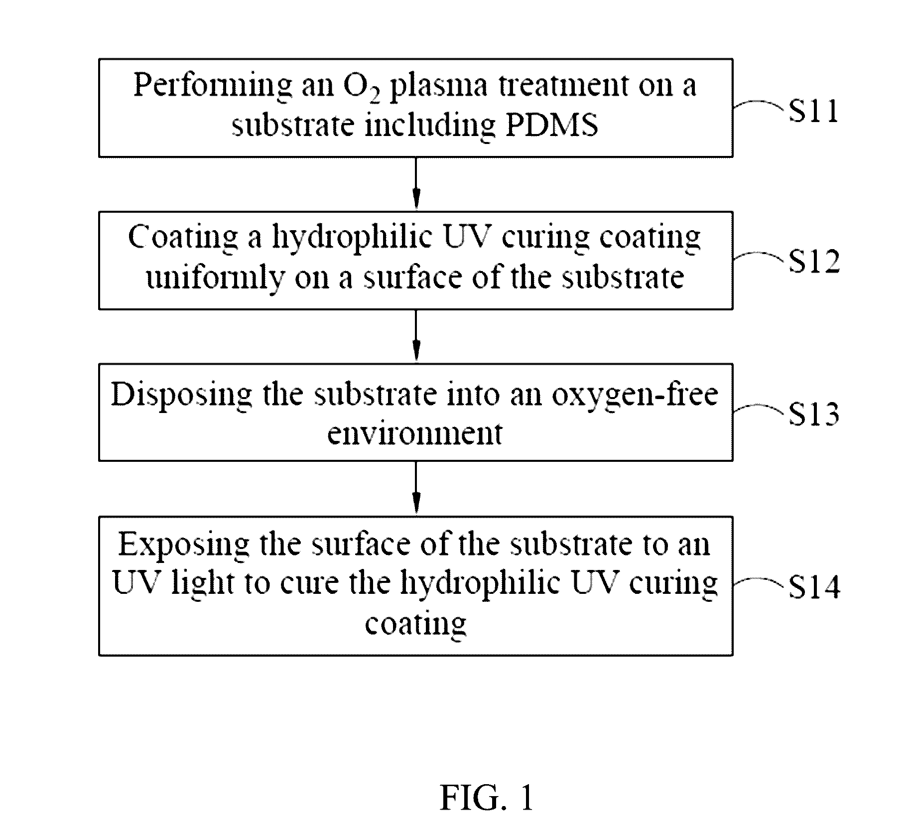
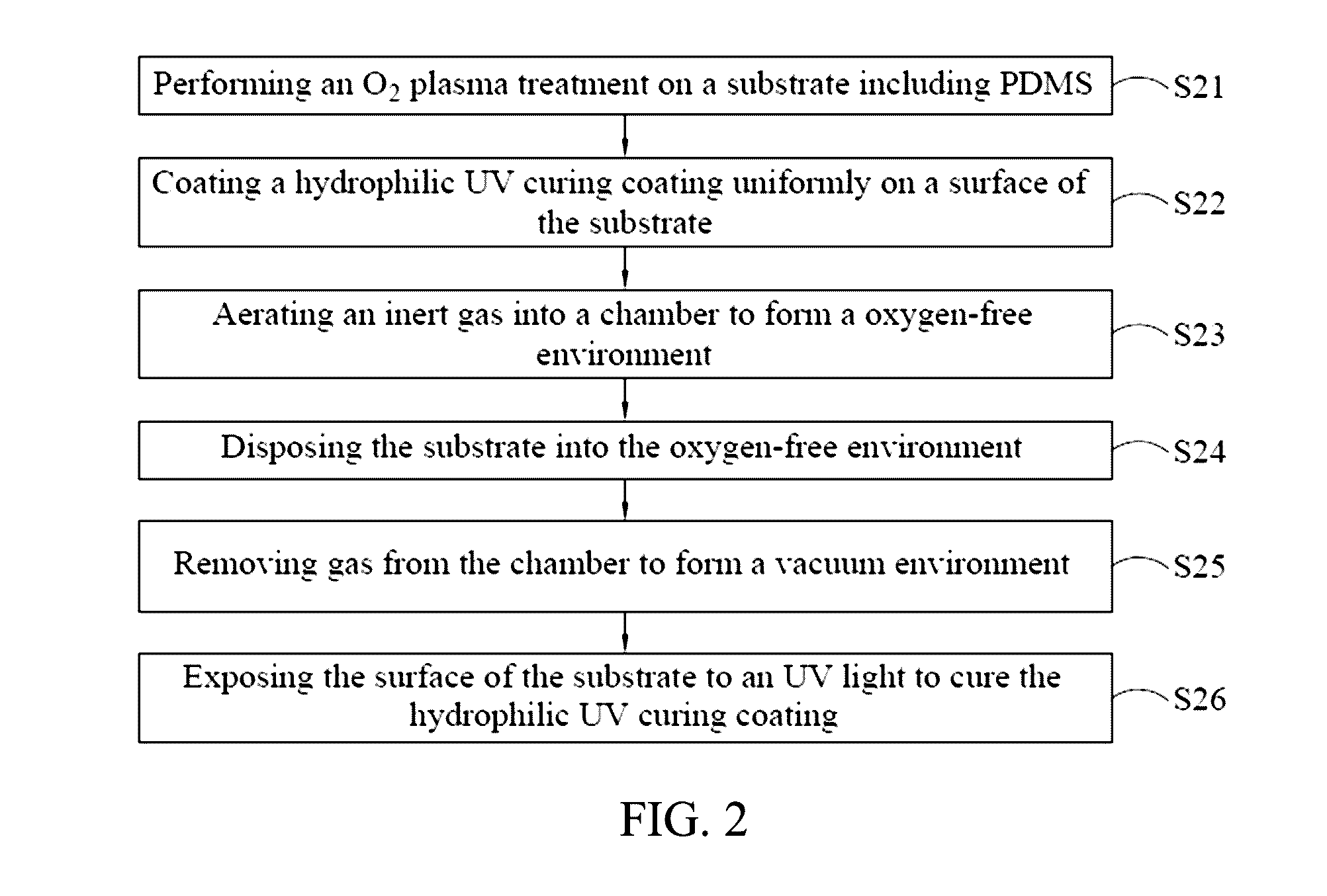
[0033]Exemplary embodiments of the present invention are described herein in the context of a method of modifying substrate surface.

[0034]Those of ordinary skilled in the art will realize that the following detailed description of the exemplary embodiment(s) is illustrative only and is not intended to be in any way limiting. Other embodiments will readily suggest themselves to such skilled persons having the benefit of this disclosure. Reference will now be made in detail to implementations of the exemplary embodiment(s) as illustrated in the accompanying drawings. The same reference indicators will be used throughout the drawings and the following detailed description to refer to the same or like parts.

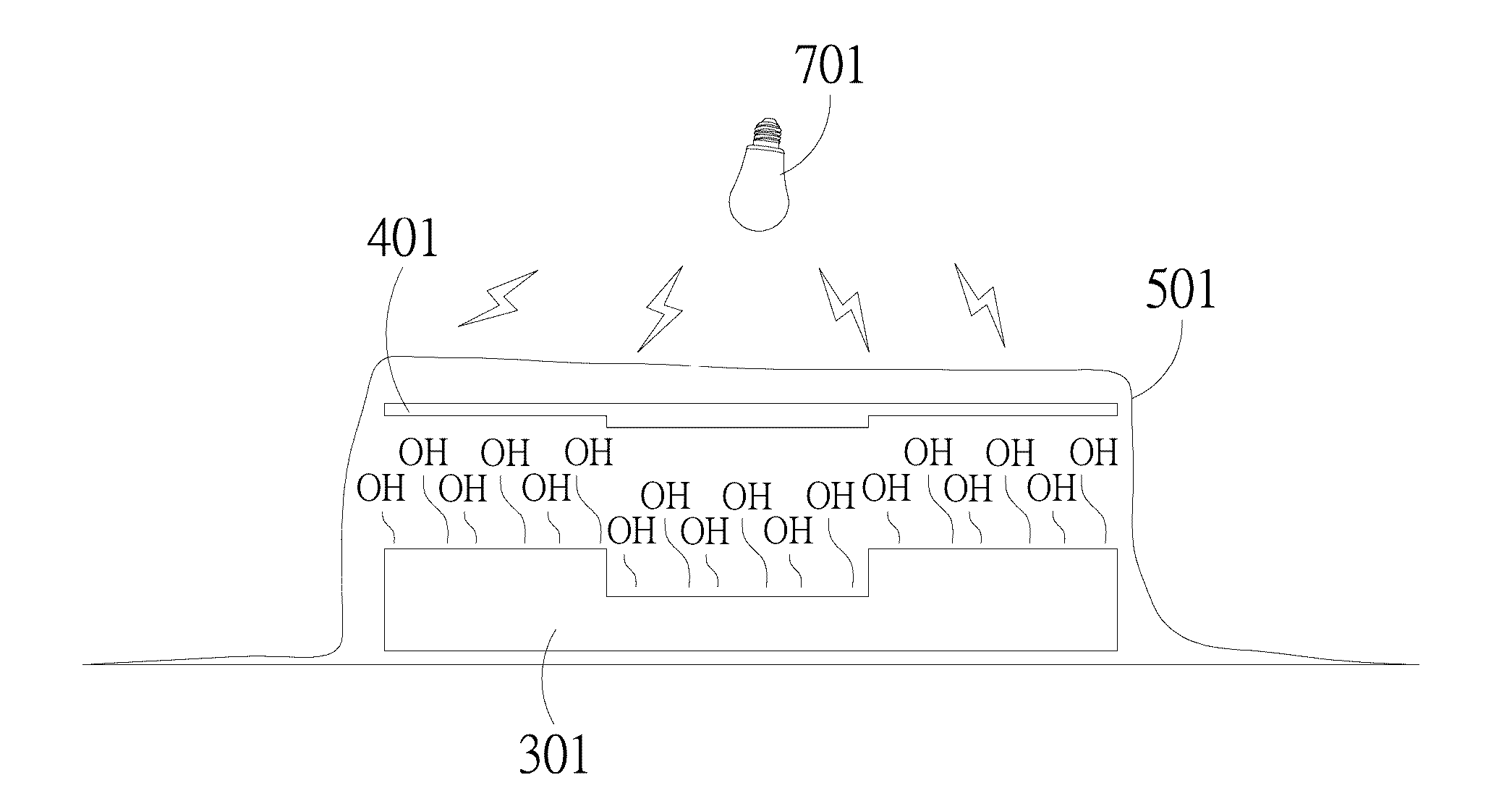
[0035]Herein, the term “substrate” refers to an object with surface being modified. The object can be made of various materials, including, but not limited to, for example, polydimethylsiloxane (PDMS). The substrate can be combined or assembled with one or more other materials, inclu...


PUM

PropertyMeasurementUnit
poweraaaaaaaaaa
temperatureaaaaaaaaaa
energyaaaaaaaaaa

Abstract

A method of modifying substrate surface includes: performing an O2 plasma treatment on a substrate including polydimethylsiloxane (PDMS); coating hydrophilic UV curing coating uniformly on the substrate; disposing the substrate into an oxygen-free environment; and exposing to an UV light to cure the hydrophilic UV curing coating. The method of modifying substrate surface may greatly enhance the hydrophilicity and the stability of the PDMS substrate.

Description

CROSS-REFERENCE TO RELATED APPLICATION[0001]This application claims priority from Taiwan Patent Application No. 104119129, filed on Jun. 12, 2015, in Taiwan Intellectual Property Office, the contents of which are hereby incorporated by reference in their entirety for all purposesBACKGROUND OF THE INVENTION[0002]Field of the Invention[0003]The exemplary embodiment(s) of the present invention relates to a field of a method of surface modification. More specifically, the exemplary embodiment(s) of the present invention relates to a method of modifying surface for substrate including polydimethylsiloxane (PDMS).[0004]Description of Related Art[0005]Microelectromechanical system has been rapid developed for decades. It combines microelectronic technology and mechanical engineering, and provides electrical machineries with operation scale within microns. Currently, the microelectromechanical system has been widely applied to a number of fields by various processing technologies. Among tho...

Claims


Application Information

Patent Timeline
Patent Type & Authority Applications(United States)
IPC IPC(8): C23C16/02C08J7/18C08J7/12C08J7/043C08J7/056
CPCC23C16/02C08J2383/04C08J7/18C08J7/123B05D3/144B29C59/14C08J3/24B29K2995/0092B29C2035/0827B05D3/0486B05D3/0493B05D3/067B05D5/00B05D7/02C08J7/0427C08J7/043C08J7/056B05D5/10C08J2433/06
Inventor LEE, GWO-BINMA, YU-DONG
Owner NATIONAL TSING HUA UNIVERSITY
Why Eureka
Try Eureka