Runner for a tidal power plant and tidal power plant comprising such a runner

Inactive Publication Date: 2016-12-15
GE RENEWABLE TECH
View PDF4 Cites 3 Cited by
  • Summary
  • Abstract
  • Description
  • Claims
  • Application Information

AI Technical Summary

Benefits of technology

The present invention provides a solution for improving the efficiency of blades in a tidal power plant by creating a runner that can work effectively in both operating modes. During reverse mode, the blades are oriented to maximize the use of hydraulic energy, resulting in a higher yield of the turbine and a more compact rotating mechanism. This design allows for increased power output from the tidal power plant.

Problems solved by technology

As a result, the orientation of the blades in reverse mode is not satisfying and involves a significant decrease of efficiency.

Method used


Image

  • Runner for a tidal power plant and tidal power plant comprising such a runner
  • Runner for a tidal power plant and tidal power plant comprising such a runner
  • Runner for a tidal power plant and tidal power plant comprising such a runner

Examples


second embodiment

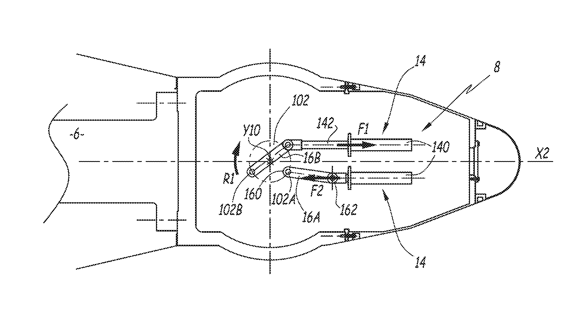
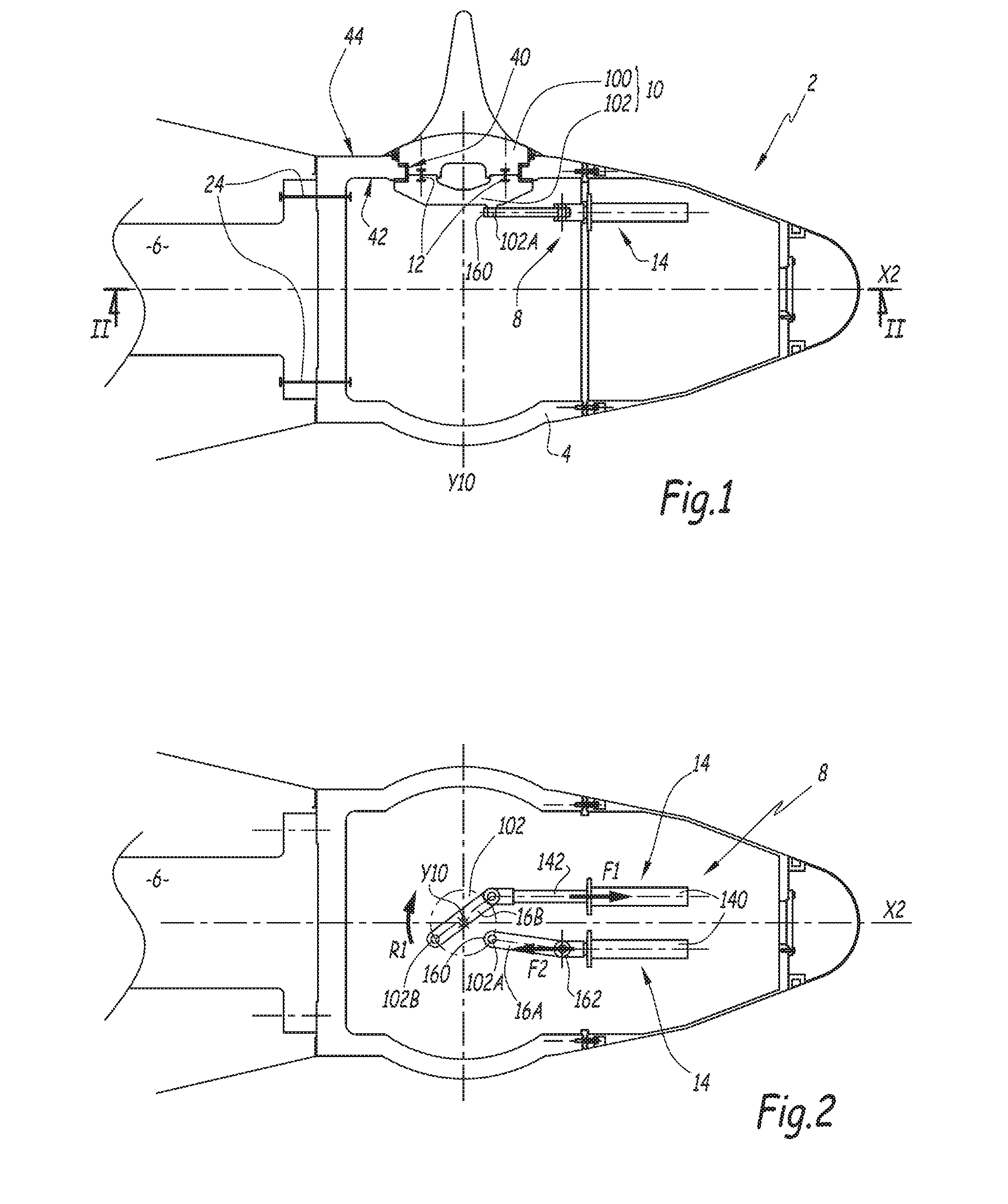
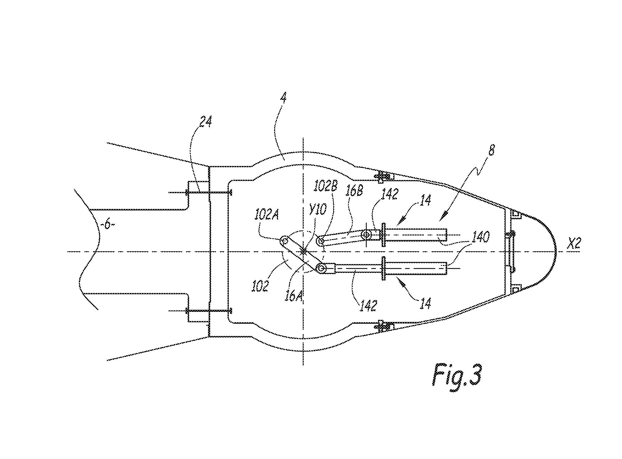
[0037]In the second embodiment, rotating means 8 includes only one linear servomotor 14 for each blade 10. This linear servomotor 14 includes a piston 52 designed for moving inside a housing 140 that is fixed with respect to the hub body 4. Rotating means 8 further include a rack 18 which is fixed at one extremity 142a of piston 142. Rack 18 prolongs then the piston 142 parallel to axis X2. Rack 18 engages a geared pinion 20 that is fixed with respect to the blade 10. In particular, geared pinion 20 is fixed with respect to blade lever 102 and centered on axis Y10. As a result, the linear displacement of piston 142 with respect to housing 140 involves the geared pinion 20 to rotate around axis Y10. The length of rack 18 together with the piston stroke of piston 142 inside housing 140 are calculated so that the blade 10 can be rotated around axis Y10 over an angle at least superior to 180°.

[0038]In a non-represented alternative embodiment, rack 18 is integral with piston 142.

third embodiment

[0039]In the third embodiment, rotating means 8 for rotating each blade 10 include an electric motor 22 and a geared pinion 20 for each blade 10. More precisely, the output shaft of motor 22 engages geared pinion 20 that is fixed with respect to the blade 10 and centered on axis Y10.

[0040]In the illustrated embodiments, the runner 2 further includes a non-represented locking mechanism for each blade 10. This locking mechanism is reversible and enables locking the orientation of a corresponding blade 10 under operating conditions, that is in two angular operative positions, respectively in direct mode and in reverse mode. In the example, this locking mechanism includes a retractable locking pin mounted on hub body 4 and means for moving locking pin from its locking position, wherein it engages a recess formed in blade lever 102, and its releasing position, wherein it is disengaged from that recess. The means for moving the locking pin comprise two chambers. The injection of fluid in ...


PUM


Abstract

A runner for a tidal power plant, comprising a hub body provided with openings for receiving blades, individual rotating means for rotating each blade with respect to the hub body, around an axis that is perpendicular to a rotation axis of the runner. The rotating means include at least one linear servomotor or an electric motor capable of rotating a corresponding blade independently of the other blades, over an angle superior or equal to 180° around its axis.

Description

TECHNICAL FIELD[0001]Embodiments of the present invention relate to a runner for a tidal power plant and a tidal power plant comprising such a runner.BACKGROUND[0002]Tidal power plants are arranged to convert into electricity the energy of tides. To this end, a turbine housing is generally arranged between the sea and a lagoon basin and the turbine housing includes a bulb runner comprising a hub body provided with openings for receiving blades. The bulb runner is integral to a rotating shaft which cooperates with an electricity generator.[0003]When the water level of the sea rises with respect to the level of the lagoon, water can start flowing through the turbine to produce energy. This corresponds to the direct mode. Similarly, as the sea level starts to fall, the tidal head can be created by holding water back in the lagoon until a sufficient head is formed. Thus, the process can be reversed and the water flows in the opposite direction from the lagoon to the sea through the turb...

Claims


Application Information

Patent Timeline
IPC IPC(8): F01D7/00F03B13/10F01D5/32F03B13/26
CPCF01D7/00F03B13/26F03B13/105F05B2270/602F05B2220/32F05B2220/706F01D5/326F03B3/145F03B13/264F05B2260/507F05B2270/328Y02E10/20Y02E10/30
Inventor BREMOND, JACQUESBERTEA, JEAN FRANCOIS
Owner GE RENEWABLE TECH
Why Eureka
Try Eureka