Rotor for a turbomachine and compressor

a technology for turbomachines and compressors, which is applied in the direction of machines/engines, stators, liquid fuel engines, etc., to achieve the effects of compact design, reduced kerosene consumption, and optimized space requirements of rotors

Inactive Publication Date: 2016-12-15
MTU AERO ENGINES GMBH
View PDF11 Cites 9 Cited by
  • Summary
  • Abstract
  • Description
  • Claims
  • Application Information

AI Technical Summary

Benefits of technology

[0032]The rotor according to the present invention advantageously makes it possible to prevent, or at least reduce, oil accumulations, for example, accumulations of bearing oil, in the inner rotor space; i.e., inside the rotor drum. In particular, by disposing the balancing flange on the radially outer side of the rotor, it is achieved that only small cavities, or no cavities at all, in which oil may accumulate (called wake regions) may be formed in the rotor drum. In an application of the rotor in an aircraft engine, this at least reduces the possibility of cabin air being contaminated by bearing oil.
[0033]The rotor according to the present invention may be used in turbines and / or compressors. By positioning the balancing ring in an axial end region of the rotor arm, it is possible to advantageously optimize the space requirements and weight of the rotor, and thus of the turbomachine. Thus, economic advantages may be obtained, for example, by reduced kerosene consumption and / or a compact design.
[0034]The placement of the balancing ring outside of the rotor drum, and thus at a larger diameter as compared to placement of the balancing ring inside of the rotor drum, may lead to a reduction in mass and weight of the flange arrangement (arrangement for form-fittingly flange-mounting another rotor main body). This may advantageously lead to a reduction in weight of the rotor stage.

Problems solved by technology

In particular, a balancing ring integrally connected to the rotor arm is not a balancing ring that could easily be mechanically detached by means of a threaded connection and / or a non-interference form-fit connection.

Method used


Image

  • Rotor for a turbomachine and compressor
  • Rotor for a turbomachine and compressor
  • Rotor for a turbomachine and compressor

Examples


Embodiment Construction

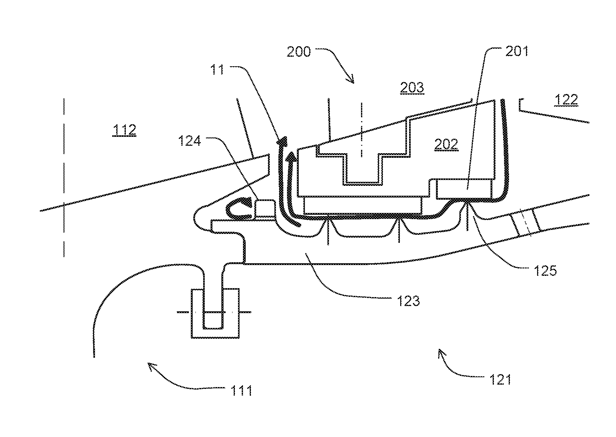
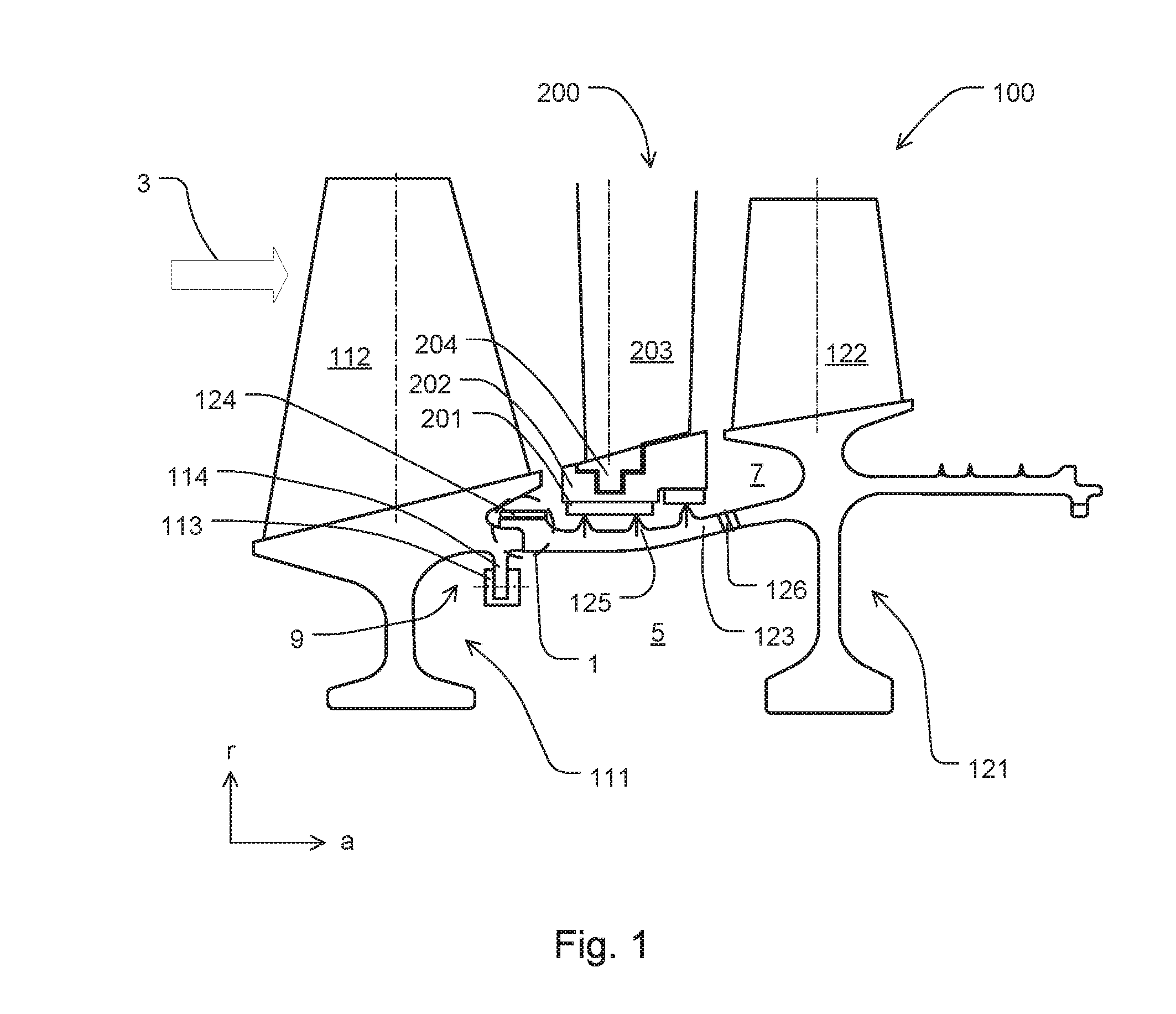
[0044]FIG. 1 shows, in cross-sectional view, an inventive rotor 100 having a balancing ring 124, a second rotor main body 121 flange-mounted to a first rotor main body 111, as well as a stator vane assembly 200.

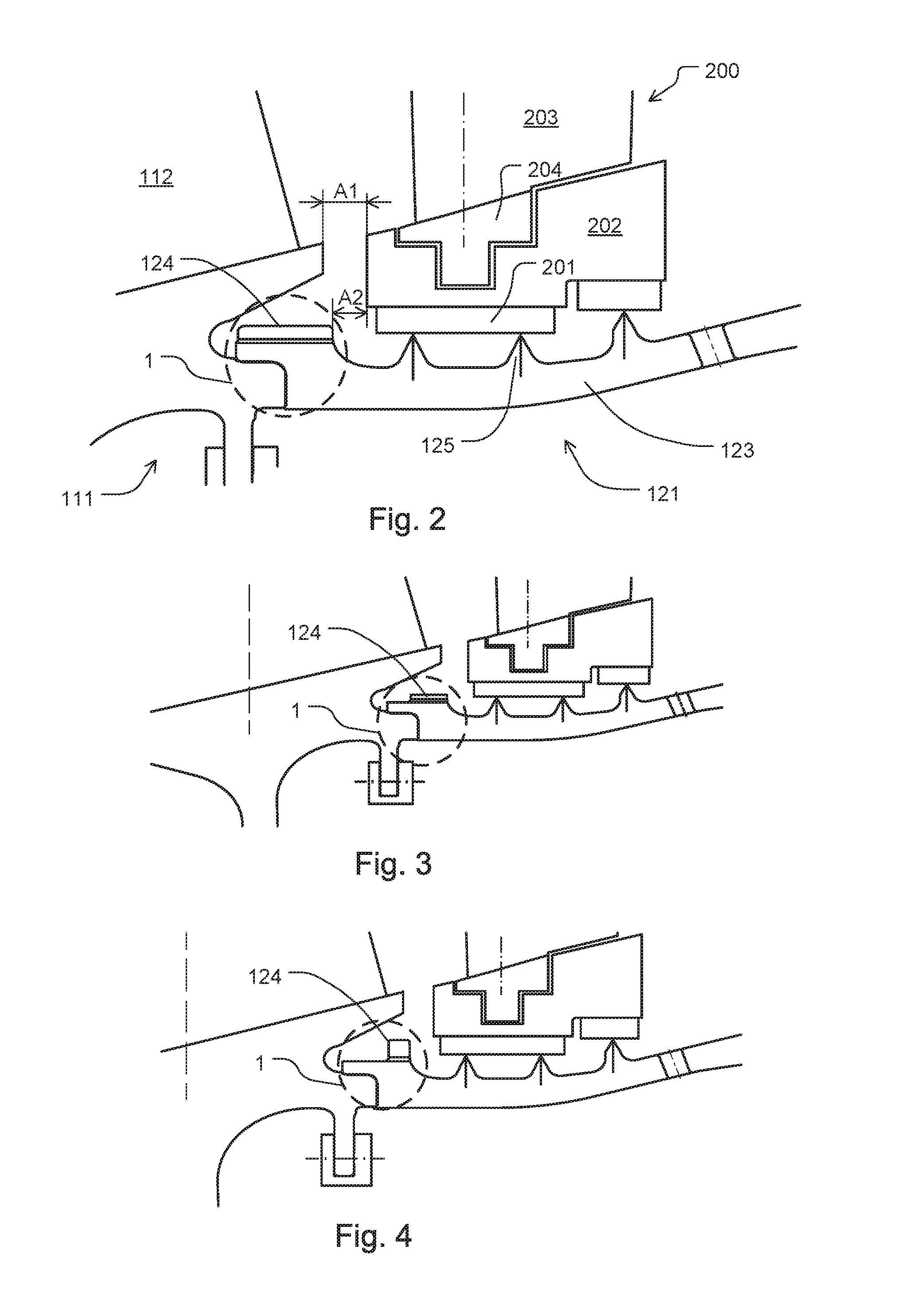
[0045]Second rotor main body 121 includes a rotor arm 123 having an arrangement 1 for form-fittingly flange-mounting second rotor main body 121 to first rotor main body 111. Arrangement 1 includes a balancing ring 124 integrally connected to rotor arm 123 at the axially forward (upstream) end of rotor arm 123. Axial direction a is oriented in main flow direction 3 of the turbomachine. Balancing ring 124 integrally connected to rotor arm 123 is frictionally connected to rotor arm 123 by an interference fit. Rotor blades 112, 122 are integrally connected to rotor main bodies 111, 121.

[0046]In FIG. 1, rotor arm 123 further has sealing tips 125 which form a gap with abradable seals 201 to minimize leakage flow between rotor 100 and a stator vane assembly 200. Abradable seals 201 ...


PUM


Abstract

A rotor for a turbomachine having at least a first rotor main body and a second rotor main body, the second rotor main body having a rotor arm having an arrangement for form-fittingly flange-mounting the first rotor main body to the second rotor main body, the arrangement having a balancing ring disposed on the radially outer side of the rotor arm is provided. The balancing ring is integrally connected to the rotor arm for form-fittingly flange-mounting the second rotor main body to the first rotor main body, the arrangement being disposed at the upstream and/or downstream end of the rotor arm. A compressor of a turbomachine having a rotor is also provided.

Description

[0001]This claims the benefit of European Patent Application EP 15166680.7, filed May 7, 2015 and hereby incorporated by reference herein.[0002]The present invention relates to a rotor for a turbomachine. The present invention also relates to a compressor.BACKGROUND[0003]Rotors for turbomachines must satisfy a variety of requirements and boundary conditions. For example, it should be possible to balance individual rotor stages to allow them to operate with little wear and low maintenance at high rotational speeds. Moreover, rotors should be optimized in terms of space requirements and have a low weight in order to satisfy economic boundary conditions such as, for example, low kerosene consumption. Finally, possible oil accumulations in cavities in the inner rotor space, such as accumulations of bearing oil, should be allowed to flow off so as to prevent possible contamination of cabin air streams by discharges from the compressor.SUMMARY OF THE INVENTION[0004]It is an object of the ...

Claims


Application Information

Patent Timeline
Patent Type & Authority Applications(United States)
IPC IPC(8): F01D11/00F04D29/54F04D29/08F04D29/32F01D5/02F01D9/04
CPCF01D11/001F01D5/02F01D9/041F05D2220/32F04D29/321F04D29/542F04D29/083F01D5/027F01D17/162F05D2260/96F05D2220/3219Y02T50/60
Inventor ALBERS, LOTHAR
Owner MTU AERO ENGINES GMBH
Why Eureka
Try Eureka