Rotary fluid element and method of correcting unbalance of rotary fluid element

a technology of rotary fluid element and rotary fluid element, which is applied in the direction of liquid fuel engine, machine/engine, instruments, etc., can solve problems such as deterioration of machine performance, and achieve the effect of sacrificing the strength of blades

Active Publication Date: 2016-12-15
MITSUBISHI HEAVY IND ENGINE & TURBOCHARGER LTD
View PDF15 Cites 27 Cited by
  • Summary
  • Abstract
  • Description
  • Claims
  • Application Information

AI Technical Summary

Benefits of technology

[0036]According to at least some embodiments of the present invention, it is possible to provide a rotary fluid element and a method of correcting unbalance of a rotary fl

Problems solved by technology

During operation of a rotary machine, the biggest factors in deterioration of p

Method used


Image

  • Rotary fluid element and method of correcting unbalance of rotary fluid element
  • Rotary fluid element and method of correcting unbalance of rotary fluid element
  • Rotary fluid element and method of correcting unbalance of rotary fluid element

Examples


Embodiment Construction

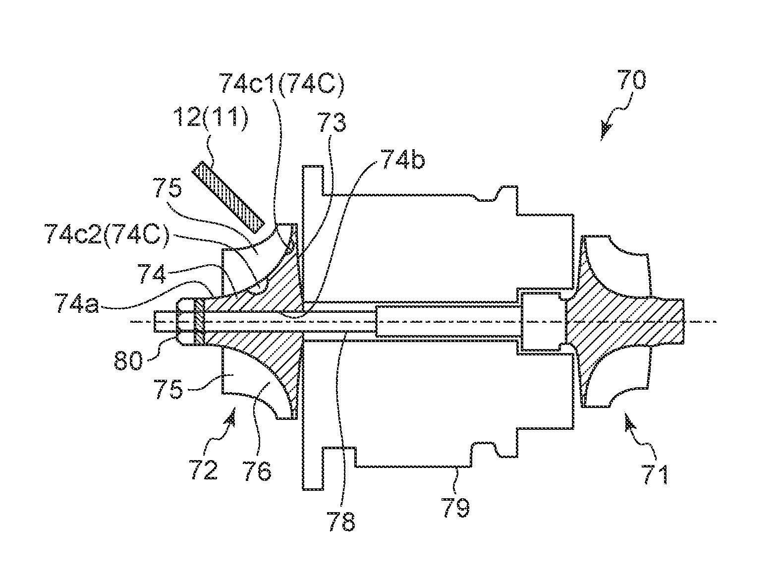
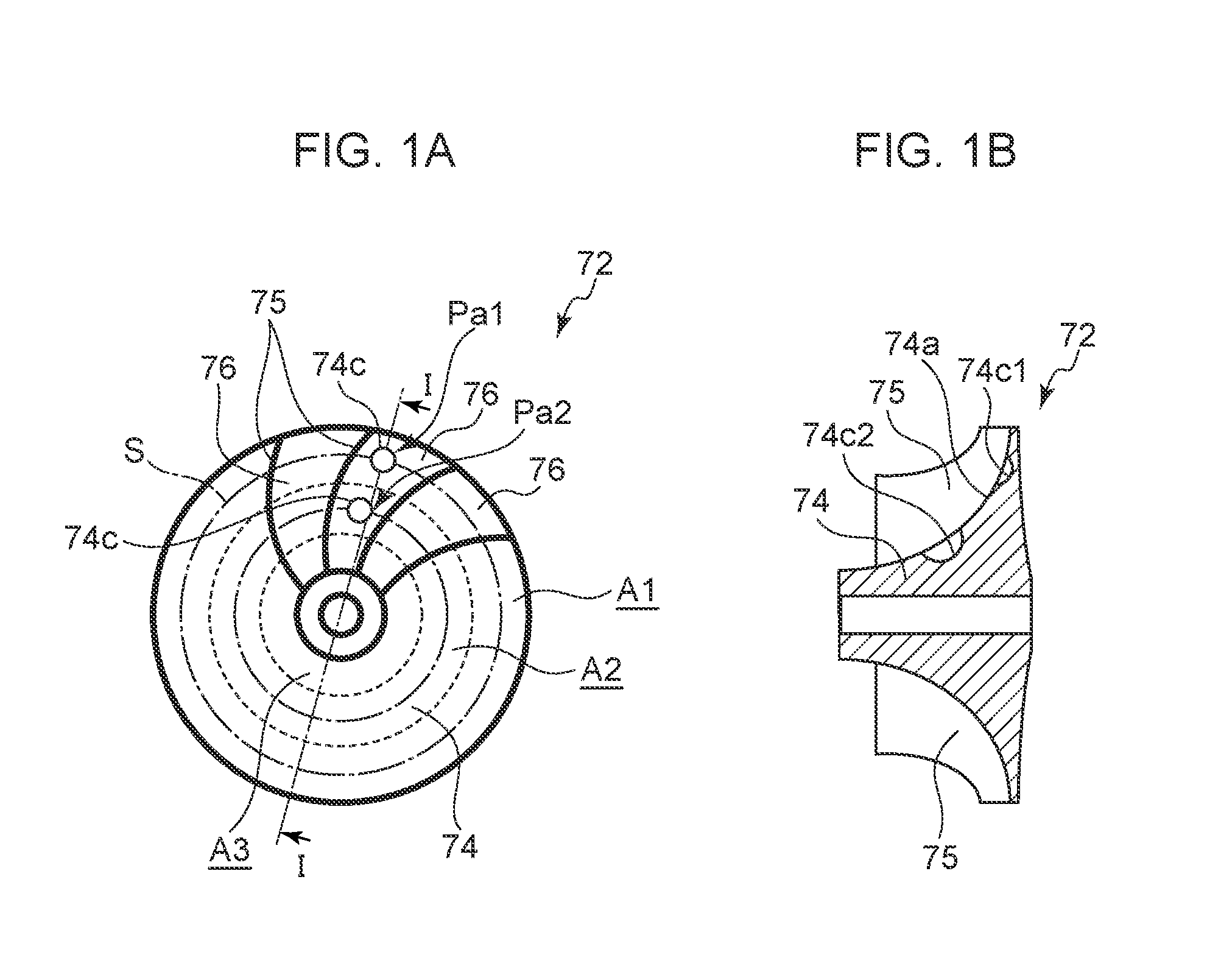
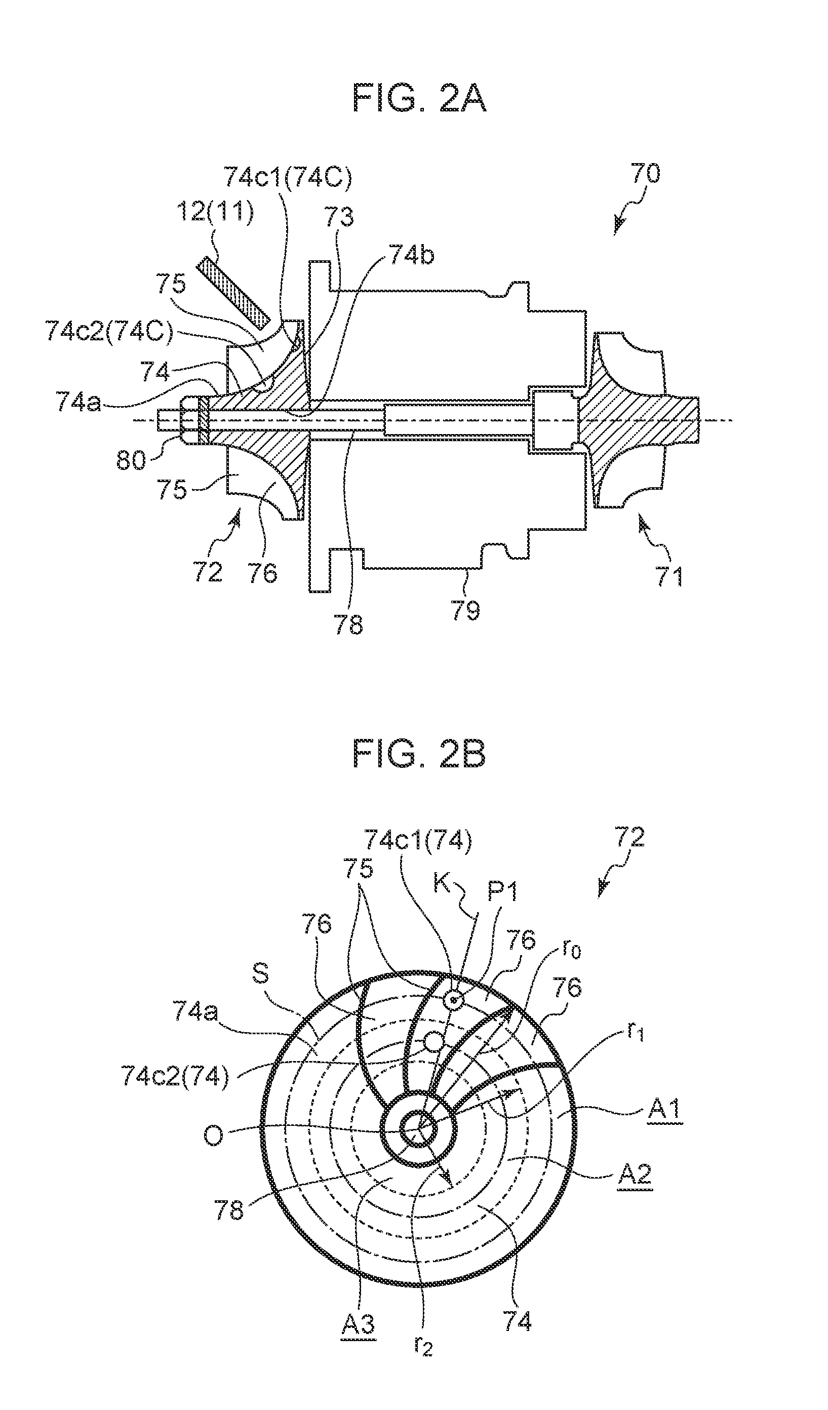
[0047]Embodiments of a rotary fluid element and a method of correcting unbalance of a rotary fluid element according to the present invention will now be described with reference to FIGS. 1 to 10. In the embodiments, a compressor wheel of a turbocharger is described as an example of a rotary fluid element. A rotary fluid element is not limited to a compressor wheel of a turbocharger, and may be a turbine wheel of a turbocharger disposed opposite from the compressor wheel. It is intended, however, that unless particularly specified, materials, shapes, relative positions and the like of components described in the embodiments shall be interpreted as illustrative only and not intended to limit the scope of the present invention.

[0048]Firstly, a turbocharger 70 to which a rotary fluid element is to be applied will be outlined, before describing a rotary fluid element and a method of correcting unbalance of a rotary fluid element according to the present invention. As depicted in FIG. 2A...


PUM


Abstract

An object is to provide a rotary fluid element and a method of correcting unbalance of a rotary fluid element, whereby unbalance of the rotary fluid element can be corrected multiple times in a necessary and sufficient amount without sacrificing strength of blades. A rotary fluid element includes: a plurality of blades extending in a centrifugal direction on an outer peripheral surface of a boss portion and disposed at intervals in a circumferential direction; and a cut-remove portion for reducing unbalance disposed in a blade gap between the blades adjacent in the circumferential direction. The cut-remove portion includes a first cut-remove portion which is cut and removed on a radially-outer rim portion between the blades, and an additional cut-remove portion which is cut and removed on a radially-inner portion disposed inside the first cut-remove portion with respect to a radial direction.

Description

TECHNICAL FIELD[0001]The present disclosure relates to a rotary fluid element including a plurality of blades extending in a centrifugal direction on an outer peripheral surface of a boss portion and disposed at intervals in a circumferential direction, as well as a method of correcting unbalance of the rotary fluid element.BACKGROUND ART[0002]In recent years, precision and speed of a rotary fluid element are more and more increasing due to advancement in technology, and thus higher performance and functionality are required. During operation of a rotary machine, the biggest factors in deterioration of performance of the machine are considered to be vibration and accompanying noise. Thus, to reduce vibration and noise, unbalance of a rotary fluid element should be corrected.[0003]In view of this, a typical method of correcting unbalance of a rotary fluid element has been performed, which is to cut and remove at least one of a part of a nut or a part of a side face of a rotary fluid ...

Claims


Application Information

Patent Timeline
IPC IPC(8): F04D29/66F01D5/02F04D29/28
CPCF04D29/662F04D29/284F05D2220/40F04D29/666F05D2230/10F01D5/027F05D2230/14F04D29/668F16F15/32G01M1/34
Inventor SEIKE, NARIAKIMORI, HIDEONAKAGAWA, HIROSHI
Owner MITSUBISHI HEAVY IND ENGINE & TURBOCHARGER LTD
Why Eureka
Try Eureka