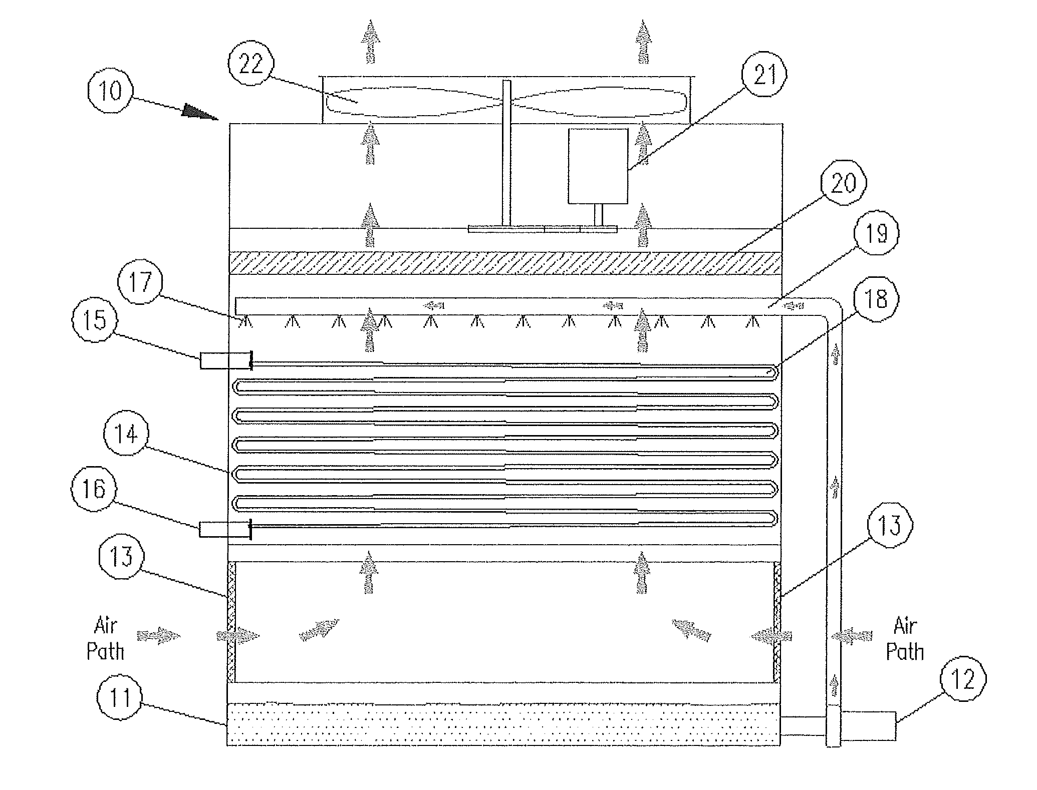
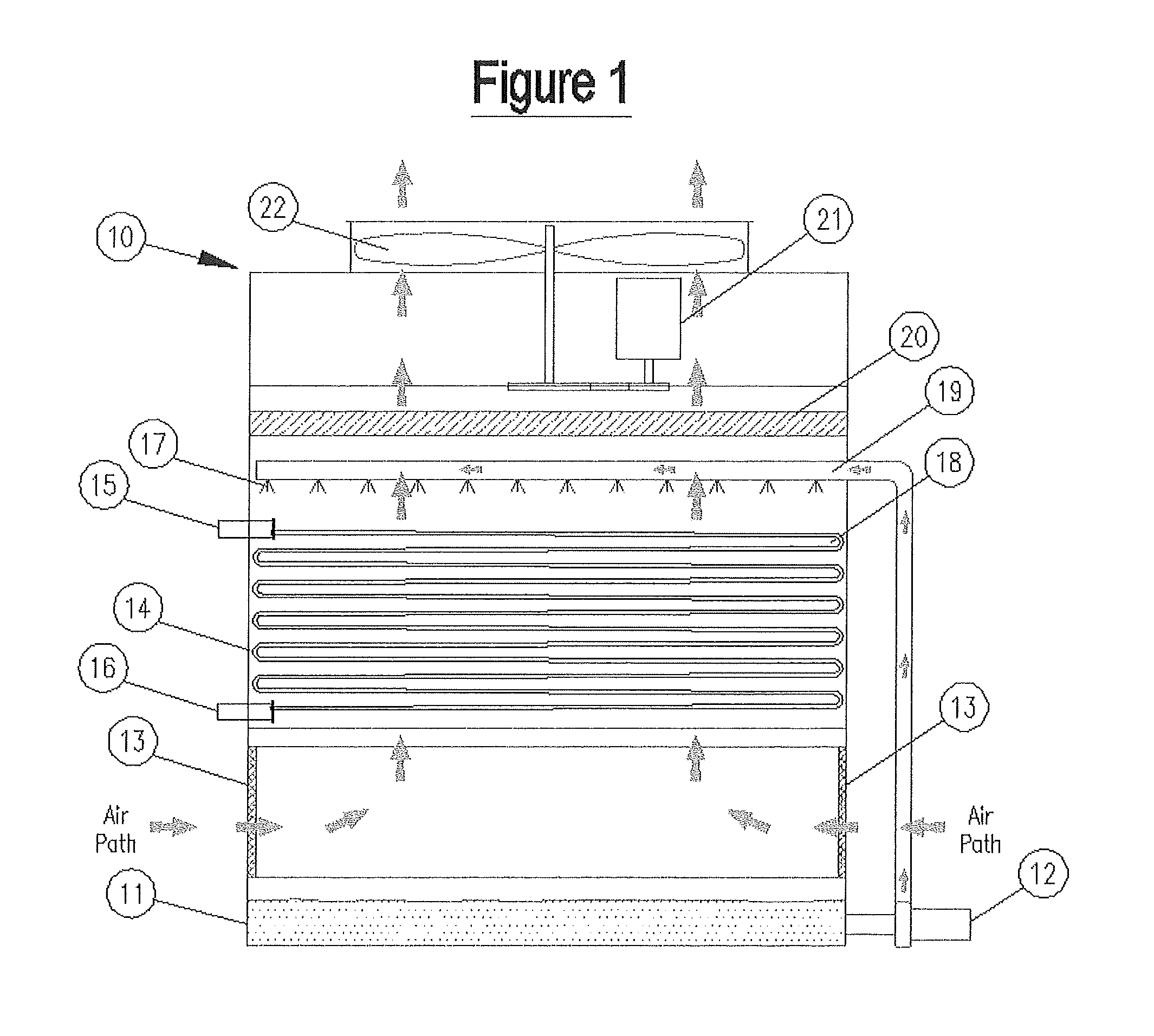
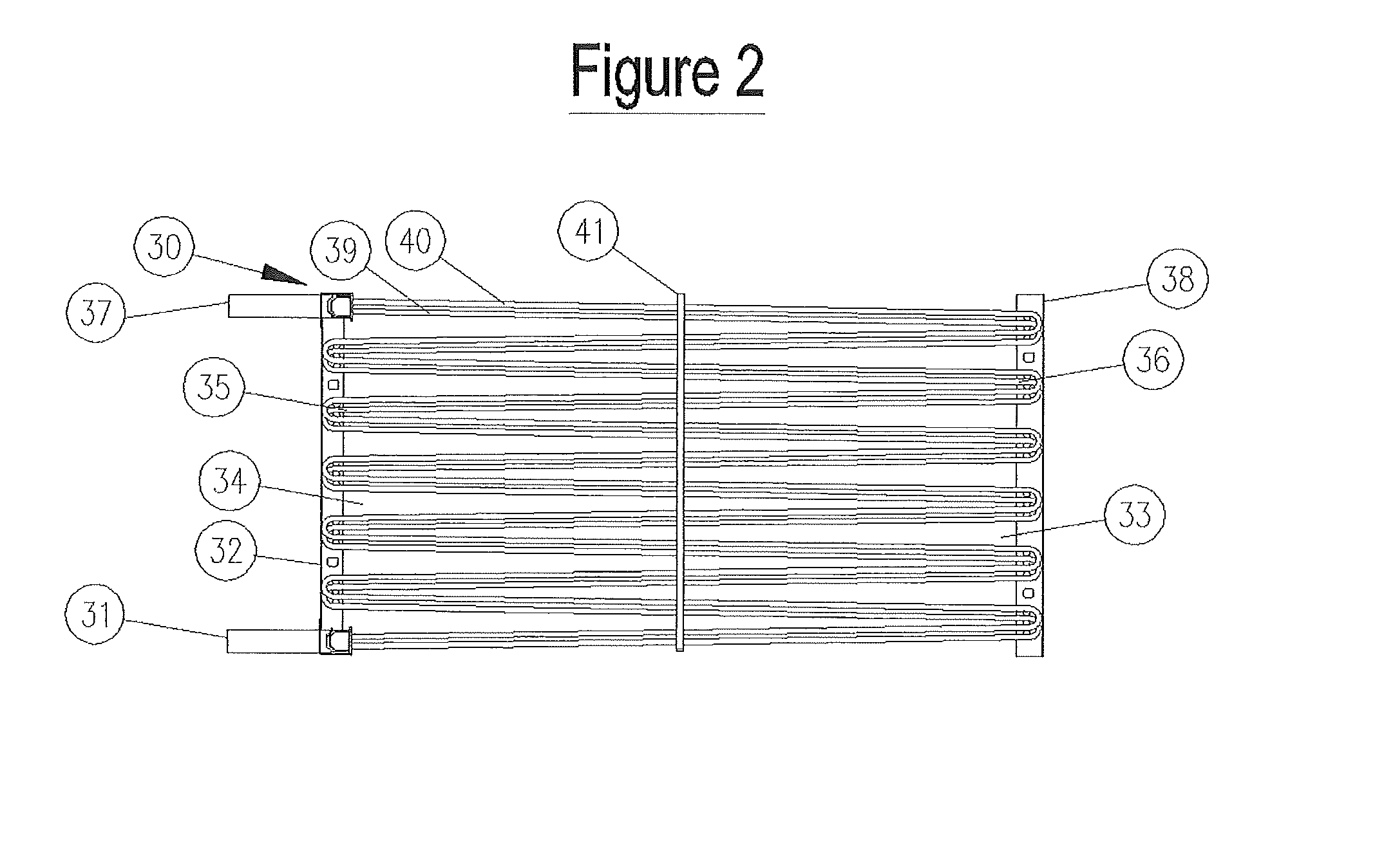
Cooling tower with indirect heat exchanger
a technology cooling tower, which is applied in the direction of indirect heat exchanger, light and heating apparatus, transportation and packaging, etc., can solve the problems of limited number of tube passes, number of return bends, and limited number of increased vertical spaces, so as to improve performance and increase distance
- Summary
- Abstract
- Description
- Claims
- Application Information
AI Technical Summary
Benefits of technology
Problems solved by technology
Method used
Image
Examples
first embodiment
[0038]Referring now to FIG. 3, a cooling tower in accordance with a first embodiment is shown at 610. In this embodiment, air enters through air inlet louvers 613, passes generally upwards through the indirect and heat exchanger 616 and also passes through optional direct heat exchanger 615 then passes through drift eliminators 622 then through fan 624 driven by fan motor 623. At the same time, when wet evaporative operation is desired, water is pumped from cold water sump 611 by pump 612 to spray header 621 and out of nozzles 620 to spray onto the top of the indirect heat exchange surface 616. Operation of the spray pump may be omitted during dry operation. Optionally, spray pump 612 may operate without fan motor 623 operating when desired, or with fan motor 623 operating between 0 to 100% speed, as known in the art. Indirect section inlet header connection 619 and outlet header connection 625 are piped to the indirect section process fluid accordingly.
[0039]In this embodiment of F...
second embodiment
[0040]Referring now to FIG. 4, a cooling tower in accordance with a second embodiment is shown at 710. In this embodiment, air enters through air inlet louvers 713, passes generally upwards through the indirect and heat exchanger 714 and also optional direct heat exchanger 715 then passes through drift eliminators 722 then through fan 724 driven by fan motor 723. At the same time, when desired, water is pumped from sump cold water 711 by pump 712 to spray header 721 and out of nozzles 720 to spray onto the top of the indirect heat exchange surface 714. Operation of the spray pump may be omitted during “dry operation”. Optionally, spray pump 712 may operate without fan motor 723 operating, or with fan motor 723 operating between 0 to 100% speed, when desired as known in the art. Indirect section inlet header connection 719 and outlet header connection 725 are piped to the indirect section process fluid accordingly.
[0041]In the embodiment of FIG. 4, all of the top and bottom indirect ...
third embodiment
[0042]Referring now to FIG. 5, a cooling tower in accordance with a third embodiment is shown at 810. In this embodiment, air enters through air inlet louvers 813, passes generally upwards through the indirect heat exchanger 818 and also optional direct heat exchanger 815 then passes through drift eliminators 822 then through fan 824 driven by fan motor 823. At the same time, when desired, water is pumped from cold water sump 811 by pump 812 to spray header 821 and out of nozzles 820 to spray onto the top of the indirect heat exchange surface 830. Operation of the spray pump may be omitted during “dry operation”. Optionally, spray pump 812 may operate without fan motor 823 operating, or with fan motor 823 operating between 0 to 100% speed, when desired as known in the art. Indirect section inlet header connection 819 and outlet header connection 825 are piped to the indirect section process fluid accordingly.
[0043]In the embodiment of FIG. 5, the indirect heat exchanger tubes have a...
PUM
| Property | Measurement | Unit |
|---|---|---|
| height | aaaaa | aaaaa |
| height | aaaaa | aaaaa |
| area | aaaaa | aaaaa |
Abstract
Description
Claims
Application Information
 - R&D
- Intellectual Property
- Life Sciences
- Materials
- Tech Scout
- Unparalleled Data Quality
- Higher Quality Content
- 60% Fewer Hallucinations
Browse by: Latest US Patents, China's latest patents, Technical Efficacy Thesaurus, Application Domain, Technology Topic, Popular Technical Reports.
© 2025 PatSnap. All rights reserved.Legal|Privacy policy|Modern Slavery Act Transparency Statement|Sitemap|About US| Contact US: help@patsnap.com


