Method and system for calculating laser beam spot size

a laser beam and spot size technology, applied in the field of optical information acquisition and process, can solve the problems of poor robustness, relative difficulty in actual operation, complicated operation, etc., and achieve the effect of simple operation, high precision and simple principl

Inactive Publication Date: 2016-12-15
SHENZHEN UNIV
View PDF1 Cites 8 Cited by
  • Summary
  • Abstract
  • Description
  • Claims
  • Application Information

AI Technical Summary

Benefits of technology

[0029]The invention has the advantageous effects that: the central position of the laser spot is firstly calculated according to a pretreatment result, then the spot radius of the laser beam is calculated through conducting Gaussian curve fitting on the central position of the laser spot without needing to firstly aligning the center of the diaphragm with the center of the spot and without needing a high precision moving device either; the method according to the invention is simple in principle and convenient in operation; moreover, the method is not affected by the incident light intensity and the exposure time of the camera, can keep the stability and high precision of the measurement results for spot images having different exposure time, and has better robustness.
that: the central position of the laser spot is firstly calculated according to a pretreatment result, then the spot radius of the laser beam is calculated through conducting Gaussian curve fitting on the central position of the laser spot without needing to firstly aligning the center of the diaphragm with the center of the spot and without needing a high precision moving device either; the method according to the invention is simple in principle and convenient in operation; moreover, the method is not affected by the incident light intensity and the exposure time of the camera, can keep the stability and high precision of the measurement results for spot images having different exposure time, and has better robustness.

Problems solved by technology

This method needs to align the center of the diaphragm with the center of the spot, which is relatively difficult in actual operation.
The method for measuring laser beam spot size based on a CCD camera includes a 1 / e2 definition method and a secondary moment definition method based on moment inalterability provided by the International Standard Organization, however both the two methods need to conduct strict decay on incident light intensity, moreover in order to ensure the precision, overexposure of a collection camera shall be prevented, and spot image grey values shall be controlled in a certain scope, resulting in complicated operation and poor robustness.

Method used


Image

  • Method and system for calculating laser beam spot size
  • Method and system for calculating laser beam spot size
  • Method and system for calculating laser beam spot size

Examples


first embodiment

[0061]Relevant theory and principle of the method for calculating laser beam spot size according to the invention are explained in the embodiment.

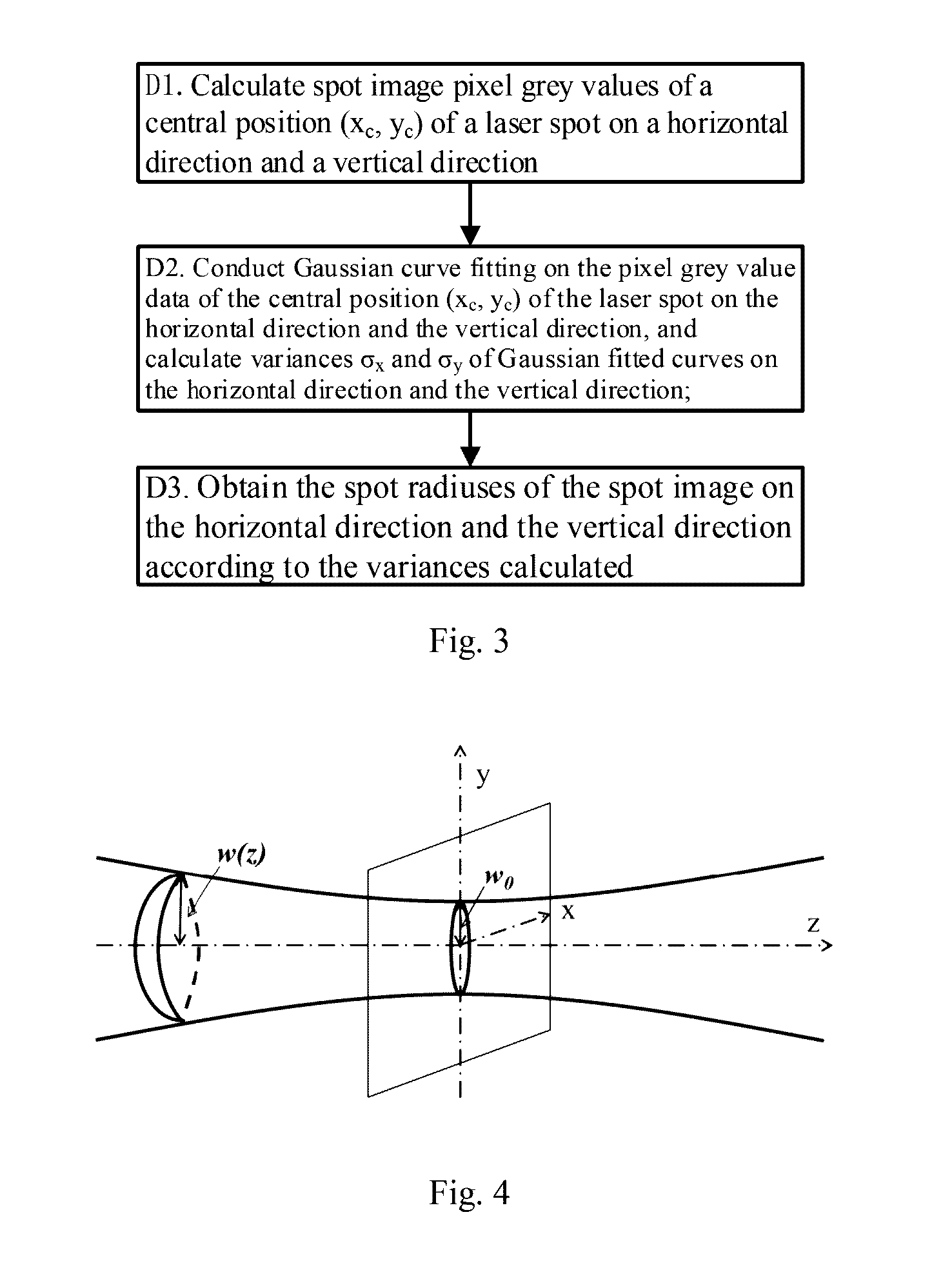
[0062]For the laser beam produced in a stable cavity with characters and spreading rules of completely different from that of a common spherical wave or plane wave, all possible types of the laser waveform are referred to as laser beam or Gaussian beam in the disclosure. FIG. 4 shows a schematic view of the laser beam spreading along an optical axis direction; no matter the field is produced by a stable cavity of any structure, the complex amplitude distribution of a field of the Gaussian beam spreading along the z axis direction can be represented in a general form as shown in the following formula (1):

E(x,y,z)=cw(z)-x2+y2w2(z)-[k(z+x2+y22R(z))-arctgzf](1)

[0063]In formula (1), x and y belong to a plane-coordinate system of a cross section of the laser beam, z indicates the direction of the laser beam spreading along an optical axis, c is ...

second embodiment

[0072]The calculation process and calculation results on the ideal laser beam spot sizes are explained in the embodiment.

[0073]FIG. 5 shows ideal laser beam spot images with different spot sizes, wherein the image resolutions are all 1025×1025, a central pixel position of the spot is (513, 513), a pixel size is 5.2 μm, and the spot sizes on the horizontal direction and the vertical direction are the same. Theoretical spot radiuses respectively corresponding to FIG. 5(a)-FIG. 5(e) respectively are 0.2 mm, 0.4 mm, 0.6 mm, 0.8 mm, and 1.0 mm in sequence.

[0074]FIG. 6 shows a schematic view of ideal laser beam spot sizes calculated using the method of the invention; a point of intersection of dotted lines on the horizontal direction and the vertical direction represents an ideal laser beam spot center, and a full line represents an ideal laser beam spot size, wherein an actual calculation data sheet is as shown in the following Table 1.

TABLE 1ActuallyActuallyActuallyActuallymeasuredmeasu...

third embodiment

[0079]A calculation process and calculation results on the laser beam spot image with different exposure time are explained in the embodiment.

[0080]FIG. 9 shows actual laser beam spot images with different exposure time. The exposure time of an industrial camera is adjusted, and spot images are collected at a certain position; the image resolutions are all set as 1280×1024, a pixel size is 5.2 μm, and exposure time respectively corresponding to FIG. 9(a)-FIG. 9(f) is 130 ms, 170 ms, 210 ms, 250 ms, 270 ms, and 290 ms in sequence.

[0081]As shown in FIG. 10, the method of the invention is employed to calculate actual laser beam spot sizes under different exposure time, wherein a point of intersection of dotted lines on the horizontal direction and the vertical direction represent an actual beam spot center, and a full time represents an actual laser beam spot size; when the exposure time is 250 ms, the pixel grey value of the spot image reaches a saturation state. An actual calculation...


PUM


Abstract

A method and system for calculating laser beam spot size, comprising: collecting a spot image of a laser beam and a corresponding background noise image along an optical axis direction; conducting pretreatment using a background subtraction method and a threshold method according to the spot image and the background noise image collected to obtain a pretreated spot image; calculating the central position of a laser spot of the pretreated spot image; and storing the pixel gray values of the spot image at the central position of the laser spot on a horizontal direction and a vertical direction, then conducting Gaussian curve fitting, calculating variances of Gaussian fitted curves on the horizontal direction and the vertical direction, and obtaining the spot radiuses of the spot image on the horizontal direction and the vertical direction according to the variances calculated.

Description

FIELD OF THE INVENTION[0001]The present invention belongs to the field of optical information acquisition and process, and particularly relates to a method and system for calculating laser beam spot size.BACKGROUND OF THE INVENTION[0002]With the continuous development of science and technology, a laser technique has been widely applied to such fields as laser manufacturing, micro machining, laser guidance, optical storage, laser medicine, etc. During the practical application process of laser, light beam quality means to evaluate the laser on the aspect of quality, which has significant meaning on designing, manufacturing, detecting and applying the laser, etc. There have been multiple index parameters for evaluating the laser beam quality at present. Different light beam quality definitions correspond to different application objects, which also reflect different emphasis points of the light beam quality. Therefore, the light beam quality shall be evaluated according to the specifi...

Claims


Application Information

Patent Timeline
Patent Type & Authority Applications(United States)
IPC IPC(8): G06T7/60G06T5/50G06T5/40
CPCG06T7/602G06T2207/20224G06T5/50G06T5/40G06T5/002G06T7/10G06T7/62
Inventor TIAN, JINDONGZHANG, LEILI, DONGTIAN, YONG
Owner SHENZHEN UNIV
Why Eureka
Try Eureka